HIKVISION DS-2CD2345G0P-I User Manual Download Page 35

Network Camera User Manual 

34 


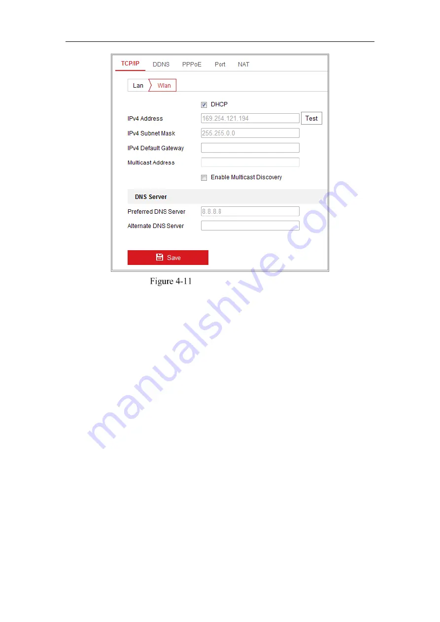
Setting WLAN Parameters 

3.


Customize the IPv4 address, the IPv4 Subnet Mask and the Default Gateway. 

The setting procedure is the same with that of LAN. 

If you want to be assigned the IP address you can check the checkbox to enable 

the DHCP.

Summary of Contents for DS-2CD2345G0P-I

Page 1: ...anual 0 User Manual UD09650B Network Camera Questo manuale d istruzione è fornito da trovaprezzi it Scopri tutte le offerte per Hikvision DS 2CD2345G0P I o cerca il tuo prodotto tra le migliori offerte di Videosorveglianza ...

Page 2: ...udes instructions for using and managing the product Pictures charts images and all other information hereinafter are for description and explanation only The information contained in the Manual is subject to change without notice due to firmware updates or other reasons Please find the latest version in the company website http overseas hikvision com en Please use this user manual under the guida...

Page 3: ... OTHER DAMAGES RESULTING FROM CYBER ATTACK HACKER ATTACK VIRUS INSPECTION OR OTHER INTERNET SECURITY RISKS HOWEVER HIKVISION WILL PROVIDE TIMELY TECHNICAL SUPPORT IF REQUIRED SURVEILLANCE LAWS VARY BY JURISDICTION PLEASE CHECK ALL RELEVANT LAWS IN YOUR JURISDICTION BEFORE USING THIS PRODUCT IN ORDER TO ENSURE THAT YOUR USE CONFORMS THE APPLICABLE LAW HIKVISION SHALL NOT BE LIABLE IN THE EVENT THAT...

Page 4: ...depending on models according to the IEC60950 1 and Limited Power Source standard To reduce the risk of fire or electrical shock do not expose this product to rain or moisture This installation should be made by a qualified service person and should conform to all the local codes Please install blackouts equipment into the power supply circuit for convenient supply interruption Please make sure th...

Page 5: ...iation To avoid heat accumulation ensure there is good ventilation to the device Keep the camera away from water and any liquids While shipping pack the camera in its original or equivalent packing materials Or packing the same texture Improper use or replacement of the battery may result in hazard of explosion Please use the manufacturer recommended battery type Notes For the camera supports IR y...

Page 6: ...Network Camera User Manual 5 body so that the foam ring and the dome cover are attached seamlessly ...

Page 7: ...tion in Manage and Ad hoc Modes 26 Easy Wi Fi Connection with WPS function 31 IP Property Settings for Wireless Network Connection 33 Chapter 5 Live View 35 Live View Page 35 Starting Live View 36 Recording and Capturing Pictures Manually 37 Operating PTZ Control 37 PTZ Control Panel 37 Setting Calling a Preset 39 Setting Calling a Patrol 40 Chapter 6 Network Camera Configuration 41 Configuring Lo...

Page 8: ...Settings 65 Configure NAT Network Address Translation Settings 67 Configure Advanced Settings 68 Configuring SNMP Settings 68 7 2 2 Configuring FTP Settings 71 7 2 3 Configuring Email Settings 73 Platform Access 75 Wireless Dial 76 HTTPS Settings 78 Configuring QoS Settings 80 Configuring 802 1X Settings 81 Integration Protocol 83 Bandwidth Adaptation 83 Network Service 84 Chapter 8 Video Audio Se...

Page 9: ...ing Audio Exception Detection 119 Configuring Defocus Detection 120 Configuring Scene Change Detection 121 Configuring Face Detection 122 Configuring Intrusion Detection 124 Configuring Line Crossing Detection 126 Configuring Region Entrance Detection 129 Configuring Region Exiting Detection 130 Configuring Unattended Baggage Detection 132 Configuring Object Removal Detection 134 VCA Configuration...

Page 10: ... Face Capture Statistics 172 People Counting Statistics 172 Heat Map Statistics 173 Counting Statistics 174 Queue Management Statistics 175 Queuing Up Time Analysis 176 Queue Status Analysis 177 Raw Data 178 Appendix 179 Appendix 1 SADP Software Introduction 179 Appendix 2 Port Mapping 182 0505601080428 ...

Page 11: ...er 8 0 and above version Apple Safari 5 0 2 and above version Mozilla Firefox 30 0 and above version and Google Chrome 31 0 and above version Note For Google Chrome 45 and its above version or Mozilla Firefox 52 and its above version which are plug in free Picture and Playback functions are hidden To use mentioned functions via web browser change to their lower version or change to Internet Explor...

Page 12: ...the network camera via a LAN Local Area Network please refer to Section 2 1 Setting the Network Camera over the LAN If you want to set the network camera via a WAN Wide Area Network please refer to Section 2 2 Setting the Network Camera over the WAN Setting the Network Camera over the LAN Purpose To view and configure the camera via a LAN you need to connect the network camera in the same subnet w...

Page 13: ... the camera first by setting a strong password for it before you can use the camera Activation via Web Browser Activation via SADP and Activation via Client Software are all supported Activation via Web Browser Steps 1 Power on the camera and connect the camera to the network 2 Input the IP address into the address bar of the web browser and click Enter to enter the activation interface Notes The ...

Page 14: ...der to increase the security of your product And we recommend you reset your password regularly especially in the high security system resetting the password monthly or weekly can better protect your product 4 Confirm the password 5 Click OK to save the password and enter the live view interface Activation via SADP Software SADP software is used for detecting the online device activating the camer...

Page 15: ...word of your own choosing using a minimum of 8 characters including at least three of the following categories upper case letters lower case letters numbers and special characters in order to increase the security of your product And we recommend you reset your password regularly especially in the high security system resetting the password monthly or weekly can better protect your product Note Yo...

Page 16: ...Modify to activate your IP address modification The batch IP address modification is supported by the SADP Refer to the user manual of SADP for details Activation via Client Software The client software is versatile video management software for multiple kinds of devices Get the client software from the supplied disk or the official website and install the software according to the prompts Follow ...

Page 17: ...Network Camera User Manual 16 the figure below Control Panel 2 Click the Device Management icon to enter the Device Management interface as shown in the figure below ...

Page 18: ...d with user name in it is not allowed STRONG PASSWORD RECOMMENDED We highly recommend you create a strong password of your own choosing using a minimum of 8 characters including at least three of the following categories upper case letters lower case letters numbers and special characters in order to increase the security of your product We recommend you reset your password regularly especially in...

Page 19: ...tton to pop up the Network Parameter Modification interface as shown in the figure below Modifying the Network Parameters 8 Change the device IP address to the same subnet with your computer by either modifying the IP address manually or checking the checkbox of Enable DHCP 9 Input the password to activate your IP address modification ...

Page 20: ...efore you start Please apply a static IP from an ISP Internet Service Provider With the static IP address you can connect the network camera via a router or connect it to the WAN directly Connecting the network camera via a router Steps 1 Connect the network camera to the router 2 Assign a LAN IP address the subnet mask and the gateway Refer to Section 2 1 2 for detailed IP address configuration o...

Page 21: ...P Directly Dynamic IP Connection Before you start Please apply a dynamic IP from an ISP With the dynamic IP address you can connect the network camera to a modem or a router Connecting the network camera via a router Steps 1 Connect the network camera to the router 2 In the camera assign a LAN IP address the subnet mask and the gateway Refer to Section 2 1 2 for detailed IP address configuration o...

Page 22: ...fter the camera is connected to a modem You need to configure the PPPoE parameters of the network camera Refer to Section 7 1 3 Configuring PPPoE Settings for detailed configuration Accessing the Camera with Dynamic IP Note The obtained IP address is dynamically assigned via PPPoE so the IP address always changes after rebooting the camera To solve the inconvenience of the dynamic IP you need to g...

Page 23: ...main name from a domain name provider 2 Configure the DDNS settings in the DDNS Settings interface of the network camera Refer to Section 7 1 2 Configuring DDNS Settings for detailed configuration 3 Visit the camera via the applied domain name ...

Page 24: ...TTPS Settings Steps 1 Open the web browser 2 In the browser address bar input the IP address of the network camera and press the Enter key to enter the login interface Note The default IP address is 192 168 1 64 You are recommended to change the IP address to the same subnet with your computer 3 Input the user name and password and click Login The admin user should configure the device accounts an...

Page 25: ...on is not required But Picture and Playback functions are hidden To use mentioned function via web browser change to their lower version or change to Internet Explorer 8 0 and above version Accessing by Client Software The product CD contains the iVMS 4200 client software You can view the live video and manage the camera with the software Follow the installation prompts to install the software The...

Page 26: ...Network Camera User Manual 25 iVMS 4200 Main View ...

Page 27: ... chapter is only applicable for the cameras with the built in Wi Fi module Configuring Wi Fi Connection in Manage and Ad hoc Modes Purpose Two connection modes are supported Choose a mode as desired and perform the steps to configure the Wi Fi Wireless Connection in Manage Mode Steps 1 Enter the Wi Fi configuration interface Configuration Network Advanced Settings Wi Fi 2 Click Search to search th...

Page 28: ... change it manually Note These parameters are exactly identical with those of the router 5 Enter the key to connect the wireless network The key should be that of the wireless network connection you set on the router Wireless Connection in Ad hoc Mode If you choose the Ad hoc mode you don t need to connect the wireless camera via a router The scenario is the same as you connect the camera and the ...

Page 29: ...less connection function for your PC 5 On the PC side search the network and you can see the SSID of the camera listed Ad hoc Connection Point 6 Choose the SSID and connect Security Mode Description Security Mode You can choose the Security Mode as not encrypted WEP WPA personal WPA enterprise WPA2 personal and WPA2 enterprise WEP mode ...

Page 30: ...ion 64 or 128 bit The encryption key length can sometimes be shown as 40 64 and 104 128 Key type The key types available depend on the access point being used The following options are available HEX Allows you to manually enter the hex key ASCII In this method the string must be exactly 5 characters for 64 bit WEP and 13 characters for 128 bit WEP WPA personal and WPA2 personal Mode Enter the requ...

Page 31: ...oad a CA certificate to present to the access point for authentication EAP PEAP User Name Enter the user name to present to the network Password Enter the password of the network PEAP Version Select the PEAP version used at the access point Label Select the label used by the access point EAPOL version Select version 1 or 2 depending on the version used at the access point CA Certificates Upload a ...

Page 32: ...r Easy Wi Fi Connection with WPS function Purpose The setting of the wireless network connection is never easy To avoid the complex setting of the wireless connection you can enable the WPS function WPS Wi Fi Protected Setup refers to the easy configuration of the encrypted connection between the device and the wireless router The WPS makes it easy to add new devices to an existing network without...

Page 33: ...rt flashing which means the WPS function of the router is enabled For detailed operation please see the user guide of the router 4 Push the WPS button to enable the function on the camera If there is not a WPS button on the camera you can also click the virtual button to enable the PBC function on the web interface 5 Click Connect button When the PBC mode is both enabled in the router and the came...

Page 34: ...he expired time for the PIN code is 120 seconds 1 Click Generate 2 Enter the code to the router in the example enter 48167581 to the router IP Property Settings for Wireless Network Connection The default IP address of wireless network interface controller is 192 168 1 64 When you connect the wireless network you can change the default IP Steps 1 Enter the TCP IP configuration interface Configurat...

Page 35: ...tting WLAN Parameters 3 Customize the IPv4 address the IPv4 Subnet Mask and the Default Gateway The setting procedure is the same with that of LAN If you want to be assigned the IP address you can check the checkbox to enable the DHCP ...

Page 36: ...ive view page Descriptions of the live view page Toolbar Live View Window Menu Bar PTZ Control Panel Preset Patrol Settings Live View Page Menu Bar Click each tab to enter Live View Playback Picture Application and Configuration page respectively Live View Window Display the live video Toolbar Toolbar allows you to adjust the live view window size the stream type and the plug ins It also allows yo...

Page 37: ...ts above version PTZ Control Perform panning tilting and zooming actions of the camera Control the light and the wiper only available for cameras supporting PTZ function Preset Patrol Settings Set call delete the presets or patrols for PTZ cameras Starting Live View In the live view window as shown in Figure 4 2 click on the toolbar to start the live view of the camera Live View Toolbar Table 5 1 ...

Page 38: ...cording please refer to Section 6 1 Note The captured image will be saved as JPEG file or BMP file in your computer Operating PTZ Control Purpose In the live view interface you can use the PTZ control buttons to realize pan tilt zoom control of the camera Note To realize PTZ control the camera connected to the network must support the PTZ function or have a pan tilt unit installed to the camera Pl...

Page 39: ...rows to realize adjustment in the relative positions For the cameras which support lens movements only the direction buttons are invalid Table 5 2 Descriptions of PTZ Control Panel Icon Description Zoom in out Focus near far Iris PTZ speed adjustment Light on off Wiper on off Auxiliary focus Initialize lens Adjust speed of pan tilt movements Start Manual Tracking Start 3D Zoom ...

Page 40: ...e lens 3 Click to finish the setting of the current preset 4 You can click to delete the preset Calling a Preset This feature enables the camera to point to a specified preset scene manually or when an event takes place For the defined preset you can call it at any time to the desired preset scene In the PTZ control panel select a defined preset from the list and click to call the preset Or you ca...

Page 41: ...ol configuration interface 2 Select a path No and click to add the configured presets 3 Select the preset and input the patrol duration and patrol speed 4 Click OK to save the first preset 5 Follow the steps above to add the other presets Figure 5 6 Add Patrol Path 6 Click OK to save a patrol 7 Click to start the patrol and click to stop it 8 Optional Click to delete a patrol ...

Page 42: ...ord files and captured pictures are the ones you record and capture using the web browser and thus the saving paths of them are on the PC running the browser Steps 1 Enter the Local Configuration interface Configuration Local Local Configuration Interface 2 Configure the following settings Live View Parameters Set the protocol type and live view performance Protocol Type TCP UDP MULTICAST and HTTP...

Page 43: ...ion is enabled as well when a face is detected it will be marked with a green rectangle on the live view Display POS Information Enable the function feature information of the detected target is dynamically displayed near the target in the live image The feature information of different functions are different For example ID and waiting time for Queue Management height for People Counting etc Note...

Page 44: ...ettings include System Settings Maintenance Security and User Management etc Configuring Basic Information Enter the Device Information interface Configuration System System Settings Basic Information In the Basic Information interface you can edit the Device Name and Device No Other information of the network camera such as Model Serial No Firmware Version Encoding Version Number of Channels Numb...

Page 45: ...cessible You need to wait 1 or 2 minutes before the upgrade finishes Configuring Time Settings Purpose You can follow the instructions in this section to configure the time synchronization and DST settings Steps 1 Enter the Time Settings interface Configuration System System Settings Time Settings Time Settings 2 Select the Time Zone of your location from the drop down menu ...

Page 46: ... camera is connected to a public network you should use a NTP server that has a time synchronization function such as the server at the National Time Center IP Address 210 72 145 44 If the camera is set in a customized network NTP software can be used to establish a NTP server for time synchronization Configure the manual time synchronization 1 Check the Manual Time Sync item to enable the manual ...

Page 47: ... be configured by using software such as HyperTerminal The serial port parameters must be the same as the serial port parameters of the camera Transparent Channel Connect a serial device directly to the camera The serial device will be controlled remotely by the computer through the network Steps 1 Enter RS232 Port Setting interface Configuration System System Settings RS232 2 Configure the Baud R...

Page 48: ...he same with the parameters you configured here 3 Click Save to save the settings Configuring RS485 Settings Purpose The RS485 serial port is used to control the PTZ of the camera The configuring of the PTZ parameters should be done before you control the PTZ unit Steps 1 Enter RS 485 Port Setting interface Configuration System System Settings RS485 ...

Page 49: ...d Rate PTZ Protocol and PTZ Address parameters should be exactly the same as the PTZ camera parameters Configuring DST Settings Purpose Daylight Saving Time DST is a way of making better use of the natural daylight by setting your clock forward one hour during the summer months and back again in the fall Configure the DST according to your actual demand Steps 1 Enter the DST configuration interfac...

Page 50: ...ia the Web browser External devices vary according to the different camera models Steps 1 Enter the External Device configuration interface Configuration System System Settings External Device External Device Settings 2 Check the Enable Supplement Light checkbox to enable the LED Light 3 Move the slider to adjust the low beam brightness and high bean brightness 4 Select the mode for LED light Timi...

Page 51: ...d when several VCA functions are available It helps allocate more resources to the desired functions VCA Resource Configuration Steps 1 Enter VCA Resource configuration interface Configuration System System Settings VCA Resource 2 Select a desired VCA combination Available VCA combination varies according to different camera models 3 Click Save to save the settings A reboot is required after setti...

Page 52: ...iguration System Maintenance Upgrade Maintenance Reboot Restart the device Restore Reset all the parameters except the IP parameters and user information to the default settings Default Restore all the parameters to the factory default Notes After restoring the default settings the IP address is also restored to the default IP address please be careful for this action For camera that supports Wi F...

Page 53: ...are directory to locate the upgrade file Firmware Locate the exact path of the upgrade file Firmware Directory Only the directory the upgrade file belongs to is required 2 Click Browse to select the local upgrade file and then click Upgrade to start remote upgrade Note The upgrading process will take 1 to 10 minutes Please don t disconnect power of the camera during the process and the camera rebo...

Page 54: ...e 3 Click Search to search log files The matched log files will be displayed on the log list interface Log Searching 4 To export the log files click Export to save the log files System Service Purpose System service settings refer to the hardware service the camera supports Supported functions vary according to the different cameras For the cameras support IR Light ...

Page 55: ...stream is not enabled by default Check Enable Third Stream to enable the function Enable Third Stream Security Settings Configure the parameters including Authentication IP Address Filter and Security Service from security interface Authentication Purpose You can specifically secure the stream data of live view Steps 1 Enter the Authentication interface Configuration System Security Authentication...

Page 56: ...urpose This function makes it possible for access control Steps 1 Enter the IP Address Filter interface Configuration System Security IP Address Filter IP Address Filter Interface 2 Check the checkbox of Enable IPAddress Filter 3 Select the type of IP Address Filter in the drop down list Forbidden and Allowed are selectable 4 Set the IP Address Filter list Add an IP Address Steps 1 Click the Add t...

Page 57: ... IP 3 Click the OK to finish modifying Delete an IP Address or IP Addresses Select the IP address es and click Delete 5 Click Save to save the settings Security Service To enable the remote login and improve the data communication security the camera provides the security service for better user experience Steps 1 Enter the security service configuration interface Configuration System Security Sec...

Page 58: ...d you can try to login the device after 30 minutes User Management User Management As Administrator The admin user can add delete or modify user accounts and grant them different permissions We highly recommend you manage the user accounts and permissions properly Enter the User Management interface Configuration System User Management Note Admin password if required for adding and modifying a use...

Page 59: ... reset your password regularly especially in the high security system resetting the password monthly or weekly can better protect your product 3 You can check or uncheck the permissions for the new user 4 Click OK to finish the user addition Modifying a User Steps 1 Left click to select the user from the list and click Modify 2 Modify the User Name Level and Password STRONG PASSWORD RECOMMENDED We...

Page 60: ...ssword Set Security Question You can set the security questions during camera activation Or you can set the function at user management interface Security question setting is not cleared when you restore the camera not to default Steps 1 Enter setting interface Configuration System User Management User Management 2 Click Security Question 3 Input correct admin password 4 Select questions and input...

Page 61: ...ed for 30 minutes after 7 failed attempts of answering security questions Online Users Purpose You can see the current users who are visiting the device through this interface User information such as user name level IP address and operation time is displayed in the User List Click Refresh to refresh the list View the Online Users ...

Page 62: ... PPPoE Port and NAT etc by following the instructions in this section Configuring TCP IP Settings Purpose TCP IP settings must be properly configured before you operate the camera over network The camera supports both the IPv4 and IPv6 Both versions can be configured simultaneously without conflicting to each other and at least one IP version should be configured Steps 1 Enter TCP IP Settings inte...

Page 63: ...st Discovery and then the online network camera can be automatically detected by client software via private multicast protocol in the LAN 4 Configure the DNS server Input the preferred DNS server and alternate DNS server 5 Click Save to save the above settings Notes The valid value range of MTU is 1280 1500 The Multicast sends a stream to the multicast group address and allows multiple clients to...

Page 64: ...u start Registration on the DDNS server is required before configuring the DDNS settings of the camera Steps 1 Enter the DDNS Settings interface Configuration Network Basic Settings DDNS 2 Check the Enable DDNS checkbox to enable this feature 3 Select DDNS Type Two DDNS types are selectable DynDNS and NO IP DynDNS Steps 1 Enter Server Address of DynDNS e g members dyndns org 2 In the Domain text f...

Page 65: ...NS Type as NO IP Figure 7 3 NO IP DNS Settings 2 Enter the Server Address as www noip com 3 Enter the Domain name you registered 4 Enter the User Name and Password 5 Click Save and then you can view the camera with the domain name Note Reboot the device to make the settings take effect ...

Page 66: ...y risks we strongly recommend the use of strong passwords for all functions and network devices The password should be something of your own choosing using a minimum of 8 characters including at least three of the following categories upper case letters lower case letters numbers and special characters in order to increase the security of your product Proper configuration of all passwords and othe...

Page 67: ...to 65535 HTTPS Port The default port number is 443 and it can be changed to any port No which is not occupied Server Port The default server port number is 8000 and it can be changed to any port No ranges from 2000 to 65535 Note When you use client software to visit the camera and you have changed the server port number you have to input the correct server port number in login interface to access ...

Page 68: ...re that provides compatibility among networking equipment software and other hardware devices The UPnP protocol allows devices to connect seamlessly and to simplify the implementation of networks in the home and corporate environments With the function enabled you don t need to configure the port mapping for each port and the camera is connected to the Wide Area Network via the router UPnP Setting...

Page 69: ...NMP function to get camera status parameters and alarm related information and manage the camera remotely when it is connected to the network Before you start Before setting the SNMP please download the SNMP software and manage to receive the camera information via SNMP port By setting the Trap Address the camera can send the alarm event and exception messages to the surveillance center Note The S...

Page 70: ... characters including at least three of the following categories upper case letters lower case letters numbers and special characters in order to increase the security of your product Proper configuration of all passwords and other security settings is the responsibility of the installer and or end user Steps 1 Enter the SNMP Settings interface Configuration Network Advanced Settings SNMP ...

Page 71: ...0 SNMP Settings 2 Check the checkbox of Enable SNMPv1 Enable SNMP v2c Enable SNMPv3 to enable the feature correspondingly 3 Configure the SNMP settings Note The settings of the SNMP software should be the same as the settings you ...

Page 72: ... v2 7 2 2 Configuring FTP Settings Purpose You can configure the FTP server related information to enable the uploading of the captured pictures to the FTP server The captured pictures can be triggered by events or a timing snapshot task Steps 1 Enter the FTP Settings interface Configuration Network Advanced Settings FTP FTP Settings 2 Input the FTP address and port 3 Configure the FTP settings an...

Page 73: ...Device Name Device Number or Device IP for the name of the directory and when the Child Directory is selected you can use the Camera Name or Camera No as the name of the directory Picture Filing Interval For better picture management you can set the picture filing interval from 1 day to 30 days Pictures captured in the same time interval will be saved in one folder named after the beginning date a...

Page 74: ...ngs Configuration Network Basic Settings TCP IP to set the IPv4 Address IPv4 Subnet Mask IPv4 Default Gateway and the Preferred DNS Server Note Please refer to Section 7 1 1 Configuring TCP IP Settings for detailed information 2 Enter the Email Settings interface Configuration Network Advanced Settings Email 3 Configure the following settings Sender The name of the email sender Sender s Address Th...

Page 75: ...server requires authentication check this checkbox to use authentication to log in to this server and input the login user name and password For your privacy and to better protect your system against security risks we strongly recommend the use of strong passwords for all functions and network devices The password should be something of your own choosing using a minimum of 8 characters including a...

Page 76: ...form Steps 1 Enter the Platform Access settings interface Configuration Network Advanced Settings Platform Access 2 Check the checkbox of Enable to enable the platform access function of the device 3 Select the Platform Access Mode Note Hik Connect is an application for mobile devices With the App you can view live image of the camera receive alarm notification and so on ...

Page 77: ...Connect Mobile Client User Manual 4 You can use the default server address Or you can check the Custom checkbox on the right and input a desired server address 5 Click Save to save the settings Wireless Dial Purpose Data stream of audio video and image can be transferred via 3G 4G wireless network Notes The wireless dial function may not be supported by some camera models Camera that supports wire...

Page 78: ...ual is selected as the dial mode 5 Input the UIM Number Mobile Phone Number 6 Click the Edit button to set the arming schedule if Auto is selected as the dial mode 7 Click Save to save the settings 4 View the dial status 1 Click the Refresh button to view the dial status including real time mode UIM status signal strength etc 2 If Manual is selected as the dial mode you can also manually connect d...

Page 79: ...or certain camera models If HTTPS is enabled the camera creates an unsigned certificate automatically When accessing via HTTPS the web browser will send a prompt that installing a signed certificate is recommended Steps 1 Enter the HTTPS settings interface Configuration Network Advanced Settings HTTPS 2 Check Enable to access the camera via HTTP or HTTPS protocol 3 Check Enable HTTPS Browsing to a...

Page 80: ...reate the request and import the authorized certificate 1 Select Create the certificate request first and continue the installation as the Installation Method 2 Click Create button to create the certificate request Fill in the required information in the popup window 3 Click Download to download the certificate request and submit it to the trusted certificate authority for signature 4 After receiv...

Page 81: ... the installation Click Browse and Install to import the certificate to the device Import the Certificate 2 5 There will be the certificate information after your successfully creating and installing the certificate Installed Certificate 6 Click the Save button to save the settings Configuring QoS Settings Purpose ...

Page 82: ...ority is Note DSCP refers to the Differentiated Service Code Point and the DSCP value is used in the IP header to indicate the priority of the data 3 Click Save to save the settings Note A reboot is required for the settings to take effect Configuring 802 1X Settings Purpose The IEEE 802 1X standard is supported by the network cameras and when the feature is enabled the camera data is secured and ...

Page 83: ...ty of your product Proper configuration of all passwords and other security settings is the responsibility of the installer and or end user Steps 1 Enter the 802 1X Settings interface Configuration Network Advanced Settings 802 1X 802 1X Settings 2 Check the Enable IEEE 802 1X checkbox to enable the feature 3 Configure the 802 1X settings including Protocol EAPOL version User Name Password and Con...

Page 84: ...able the function 2 Add ONVIF users Up to 32 users are allowed Set the user name and password and confirm the password You can set the user as media user operator and administrator Note ONVIF user account is different from the camera user account You have set ONVIF user account independently 3 Save the settings Note User settings of ONVIF are cleared when you restore the camera Bandwidth Adaptatio...

Page 85: ...ain camera model WebSocket or WebSockets protocol are used for plug in free live view When you use Google Chrome 45 and its above version or Mozilla Firefox 52 and its above version to visit your camera you should enable WebSocket or Websokets protocol Otherwise live view image capture and digital zoom function are not usable If the camera uses HTTP enable WebSocket If the camera uses HTTPS enable...

Page 86: ...eo Settings For certain camera models you can configure parameters for available video streams for example the main stream the sub stream etc And you can also customize additional video streams for further needs On Video page set up available video streams On Custom Video page add extra video streams Video Settings Steps 1 Enter the Video Settings interface Configuration Video Audio Video ...

Page 87: ... is usually for recording and live view with good bandwidth and the sub stream can be used for live view when the bandwidth is limited 3 You can customize the following parameters for the selected stream type Video Type Select the stream type to video stream or video audio composite stream The audio signal will be recorded only when the Video Type is Video Audio Resolution Select the resolution of...

Page 88: ...4 H 265 MJPEG and MPEG4 Supported encoding type for different stream types may differ H 265 is a new encoding technology Compared with H 264 it reduces the transmission bitrate under the same resolution frame rate and image quality Note Selectable video encoding types may vary according to different camera modes H 264 and H 265 H 264 If you set the main stream as the stream type and H 264 as the v...

Page 89: ... bitrate distribution according the requirements of the actual scene in order to realize the set maximum average bitrate in the long term The camera needs at least 24 hours to adapt to a fixed monitoring scene Max Average Bitrate When you set a maximum bitrate its corresponding recommended maximum average bitrate will be shown in the Max Average Bitrate box You can also set the maximum average bit...

Page 90: ...t fluent 4 Click Save to save the settings Note The video parameters vary according to different camera models Refer to the actual display page for camera functions Custom Video You can set up to 5 additional video streams if required For custom video streams you can live view them but cannot record or playback them Notes Custom video function requires the support of the camera After a camera rest...

Page 91: ...or the stream name 3 Customize the stream parameters resolution frame rete max bitrate video encoding For parameter introduction see Section 8 1 1 4 Optional Add stream description is needed 5 Optional If a custom stream is not needed click to delete it 6 Save the settings Configuring Audio Settings Steps 1 Enter the Audio Settings interface Configuration Video Audio Audio ...

Page 92: ...and pickup respectively Input Volume 0 100 adjustable Environmental Noise Filter Set it as OFF or ON When the function is enabled the noise in the environment can be filtered to some extent 3 Click Save to save the settings Configuring ROI Encoding Purpose ROI Region of Interest encoding helps to discriminate the ROI and background information in video compression which means the technology assign...

Page 93: ...ngs interface Configuration Video Audio ROI 2 Select the Stream Type for ROI encoding 3 Check the checkbox of Enable under Fixed Region item 4 Set Fixed Region for ROI 1 Select the Region No from the drop down list 2 Check the Enable checkbox to enable ROI function for the chosen region ...

Page 94: ...egion for ROI 1 Check the checkbox to enable Face Tracking Note To enable face tracking function the face detection function should be supported and enabled 2 Select the ROI level 6 Click Save to save the settings Note ROI level means the image quality enhancing level The larger the value is the better the image quality would be Display Info on Stream Check the checkbox of Enable Dual VCA and the ...

Page 95: ...et cropping function varies according to different camera models Steps 1 Enter the Target Cropping settings interface 2 Check Enable Target Cropping checkbox to enable the function 3 Set Third Stream as the stream type 4 Select the cropping resolution for the video display of target area A red rectangle is displayed on the live video to mark the target area and you can click and drag the rectangle...

Page 96: ...se Configure the image adjustment exposure settings day night switch backlight settings white balance image enhancement video adjustment and other parameters in display settings Note The display parameters vary according to the different camera models Please refer to the actual interface for details Day Night Auto Switch Steps 1 Enter the Display Settings interface Configuration Image Display Sett...

Page 97: ...uipped with the fixed lens only Manual is selectable and the iris mode is not configurable If Auto is selected you can set the auto iris level from 0 to 100 The Exposure Time refers to the electronic shutter time which ranges from 1 to 1 100 000s Adjust it according to the actual luminance condition Gain of image can also be manually configured from 0 to 100 The bigger the value is the brighter wo...

Page 98: ...s the easier the mode switches The Filtering Time refers to the interval time between the day night switch You can set it from 5s to 120s Scheduled Switch Set the start time and the end time to define the duration for day night mode Triggered by alarm input The switch is triggered by alarm input You can set the triggered mode to day or night Smart Supplement Light Set the supplement light as ON an...

Page 99: ...C area WDR Wide Dynamic Range can be used when there is a high contrast of the bright area and the dark area of the scene HLC High Light Compression function can be used when there are strong lights in the scene affecting the image quality White Balance White balance is the white rendition function of the camera used to adjust the color temperature according to the environment White Balance Image ...

Page 100: ... a normal view of the scene with 9 16 aspect ratio to ignore the needless information such as the wall and get more meaningful information of the scene Scene Mode Choose the scene as indoor or outdoor according to the real environment Video Standard 50 Hz and 60 Hz are selectable Choose according to the different video standards normally 50 Hz for PAL standard and 60 Hz for NTSC standard Lens Dist...

Page 101: ...clock in the morning and stopped at 1 o clock early in the next morning 2 Click Common tab to configure the common parameters applicable to the day mode and night mode Note For the detailed information of each parameter please refer to Section 9 1 1 Day Night Auto Switch 3 Click Day tab to configure the parameters applicable for day mode 4 Click Night tab to configure the parameters applicable for...

Page 102: ...wn list to set the time format date format display mode OSD size and OSD color 6 Configure the text overlay settings 1 Check the checkbox in front of the textbox to enable the on screen display 2 Input the characters in the textbox Note Up to 8 text overlays are configurable 7 Adjust the position and alignment of text frames Left align right align and custom are selectable If you select custom you...

Page 103: ... viewed and recorded Steps 1 Enter the Privacy Mask Settings interface Configuration Image Privacy Mask 2 Check the checkbox of Enable Privacy Mask to enable this function 3 Click Draw Area Privacy Mask Settings 4 Click and drag the mouse in the live video window to draw the mask area Note You are allowed to draw up to 4 areas on the same image 5 Click Stop Drawing to finish drawing or click Clear...

Page 104: ...teps 1 Enter the Picture Overlay Settings interface Configuration Image Picture Overlay Picture Overlay 2 Click Browse to select a picture 3 Click Upload to upload it 4 Check Enable Picture Overlay checkbox to enable the function 5 Set X Coordinate and Y Coordinate values adjust the picture position on the image Adjust Picture Width and Picture Height to the desired size 6 Click Save to save setti...

Page 105: ...Network Camera User Manual 104 128 128 ...

Page 106: ...n to be pushed to PC or mobile client software as soon as the alarm is triggered 10 1 1Configuring Motion Detection Purpose Motion detection detects the moving objects in the configured surveillance area and a series of actions can be taken when the alarm is triggered In order to detect the moving objects accurately and reduce the false alarm rate normal configuration and expert configuration are ...

Page 107: ... objected displayed with the green rectangles Select disable rules from Configuration Local Configuration Live View Parameters rules Enable Motion Detection 4 Click Draw Area Click and drag the mouse on the live video to draw a motion detection area Click Stop Drawing to finish drawing one area 5 Optional Click Clear All to clear all of the areas 6 Optional Move the slider to set the sensitivity o...

Page 108: ...t the arming schedule 2 Click on the time bar and drag the mouse to select the time period Arming Schedule Note Click on the selected time period you can adjust the time period to the desired time by either moving the time bar or input the exact time period 3 Optional Click Delete to delete the current arming schedule or click Save to ...

Page 109: ...veillance Center Upload to FTP Memory Card NAS Trigger Channel and Trigger Alarm Output are selectable You can specify the linkage method when an event occurs Linkage Method Note The linkage methods vary according to the different camera models Audible Warning Trigger the audible warning locally And it only supported by the device that have the audio output Notify Surveillance Center Send an excep...

Page 110: ... capture number The captured image can also be uploaded to the available SD card or network disk Trigger Channel The video will be recorded when the motion is detected You have to set the recording schedule to realize this function Please refer to Section 11 1 for detailed information Trigger Alarm Output Trigger one or more external alarm outputs when an event occurs Note To trigger an alarm outp...

Page 111: ...d area 5 Set the arming schedule and linkage method as in the normal configuration mode 6 Click Save to save the settings Day Night Auto Switch Steps 1 Draw the detection area as in the normal configuration mode Up to 8 areas are supported 2 Select Auto Switch for Switch Day and Night Settings 3 Select the area by clicking the area No 4 Slide the cursor to adjust the sensitivity and proportion of ...

Page 112: ... 5 Slide the cursor to adjust the sensitivity and proportion of object on the area for the selected area in the daytime 6 Slide the cursor to adjust the sensitivity and proportion of object on the area for the selected area at night 7 Set the arming schedule and linkage method as in the normal configuration mode 8 Click Save to save the settings 10 1 2Configuring Video Tampering Alarm Purpose You ...

Page 113: ...Motion Detection in Section 10 1 1 4 Check the checkbox to select the linkage method taken for the video tampering Please refer to Task 3 Set the Linkage Method for Motion Detection in Section 10 1 1 5 Click Save to save the settings 10 1 3Configuring Alarm Input Steps 1 Enter the Alarm Input Settings interface Configuration Event Basic Event Alarm Input 2 Choose the alarm input No and the Alarm T...

Page 114: ...Task 2 Set the Arming Schedule for Motion Detection in Section 10 1 1 4 Click Linkage Method and check the checkbox to select the linkage method taken for the alarm input Refer to Task 3 Set the Linkage Method for Motion Detection in Section 10 1 1 5 You can copy your settings to other alarm inputs 6 Click Save to save the settings ...

Page 115: ...ut optional 3 The Delay time can be set to 5sec 10sec 30sec 1min 2min 5min 10min or Manual The delay time refers to the time duration that the alarm output remains in effect after alarm occurs 4 Click Arming Schedule to enter the Edit Schedule Time interface The time schedule configuration is the same as the settings of the arming schedule for motion detection Refer to Task 2 Set the Arming Schedu...

Page 116: ...ken for the Exception alarm Refer to Task 3 Set the Linkage Method for Motion Detection in Section 10 1 1 Exception Settings 3 Click Save to save the settings 10 1 6Configuring Other Alarm Note Some certain cameras support Wireless Alarm PIR passive infrared sensor Alarm or Emergency Alarm Wireless Alarm Purpose When wireless alarm signal is sent to the camera from the detector such as the wireles...

Page 117: ...le Wireless Alarm to activate the wireless alarm 4 Input the alarm name in the text field as desired 5 Check the checkbox to select the linkage methods taken for the wireless alarm 6 Click Save to save the settings 7 Locate the external wireless device beside the camera and go to Configuration System System Settings Remote Control to arm the camera and study the wireless alarm Figure 10 11 Configu...

Page 118: ... Settings interface Configuration Advanced Configuration Basic Event PIR Alarm Figure 10 12 Setting PIR Alarm 2 Check the checkbox of Enable to activate the PIR alarm function 3 Input the alarm name in the text field as desired 4 Check the checkbox to select the linkage methods taken for the PIR alarm 5 Click the Edit button to set the arming schedule 6 Click Save to save the settings 7 Go to Conf...

Page 119: ...stem System Settings Remote Control to study the remote control first Steps 1 Enter the Emergency Alarm Settings interface Configuration Event Basic Event Emergency Alarm Setting Emergency Alarm 2 Check the checkbox to select the linkage methods taken for the Emergency alarm 3 Click Save to save the settings Smart Events You can configure the smart events by following the instructions in this sect...

Page 120: ...scene such as the sudden increase decrease of the sound intensity and some certain actions can be taken when the alarm is triggered Note Audio exception detection function varies according to different camera models Steps 1 Enter the Audio Exception Detection settings interface Configuration Event Smart Event Audio Exception Detection Audio Exception Detection 2 Check the checkbox of Audio Loss Ex...

Page 121: ...ccording to the real environment You can view the real time volume of the sound on the interface 5 Click Arming Schedule to set the arming schedule Refer to Task 2 Set the Arming Schedule for Motion Detection in Section 10 1 1 for detailed steps 6 Click Linkage Method and select the linkage methods for audio exception including Notify Surveillance Center Send Email Upload to FTP Memory Card NAS Tr...

Page 122: ...Notify Surveillance Center Send Email and Trigger Alarm Output 5 Click Save to save the settings Configuring Scene Change Detection Purpose Scene change detection function detects the change of surveillance environment affected by the external factors such as the intentional rotation of the camera Some certain actions can be taken when the alarm is triggered Note Scene change detection function va...

Page 123: ...set the arming schedule Refer to Task 2 Set the Arming Schedule for Motion Detection in Section 10 1 1 for detailed steps 5 Click Linkage Method to select the linkage methods for scene change including Notify Surveillance Center Send Email Upload to FTP Memory Card NAS Trigger Channel and Trigger Alarm Output 6 Click Save to save the settings Configuring Face Detection Purpose Face detection funct...

Page 124: ...ected face on the live video go to Configuration Local to enable the Rules 4 Click and drag the slider to set the detection sensitivity The Sensitivity ranges from 1 to 5 The higher the value is the more easily the face can be detected 5 Click Arming Schedule to set the arming schedule Refer to Task 2 Set the Arming Schedule for Motion Detection in Section 10 1 1 for detailed steps 6 Click Linkage...

Page 125: ...ehicle or other objects which enter and loiter in a pre defined virtual region and some certain actions can be taken when the alarm is triggered Note Intrusion detection function varies according to different camera models Steps 1 Enter the Intrusion Detection settings interface Configuration Event Smart Event Intrusion Detection Intrusion Detection ...

Page 126: ...rigger detection Min Size The minimum size of a valid target Targets with smaller sizes would not trigger detection 7 Click Stop Drawing when finish drawing 8 Set the time threshold for intrusion detection Threshold Range 0s 10s the threshold for the time of the object loitering in the region If you set the value as 0 alarm is triggered immediately after the object entering the region 9 Drag the s...

Page 127: ...er Send Email Upload to FTP Memory Card NAS Trigger Channel and Trigger Alarm Output 13 Click Save to save the settings Configuring Line Crossing Detection Purpose Line crossing detection function detects people vehicle or other objects which cross a pre defined virtual line and some certain actions can be taken when the alarm is triggered Note Line crossing detection function varies according to ...

Page 128: ...and a virtual line is displayed on the live video 5 Drag the line and you can locate it on the live video as desired Click on the line two red squares are displayed on each end and you can click and drag one of the red squares to define the shape and length of the line 6 Set the Max Size and Min Size for valid targets Targets smaller or larger than the valid target size are not able to trigger det...

Page 129: ...ity Range 1 100 It stands for the percentage of the body part of an acceptable target that goes across the pre defined line Sensitivity 100 S1 ST 100 S1 stands for the target body part that goes across the pre defined line ST stands for the complete target body Example if you set the value as 60 the action can be counted as a line crossing action only when 40 percent or more body part goes across ...

Page 130: ...fined virtual region from the outside place and some certain actions can be taken when the alarm is triggered Steps 1 Enter the Region Entrance Detection settings interface Configuration Event Smart Event Region Entrance Detection Region Entrance Detection 2 Check the Enable checkbox to enable the function 3 Select the Region from the drop down list for detection settings ...

Page 131: ...for the percentage of the body part of an acceptable target that enters the pre defined region Sensitivity 100 S1 ST 100 S1 stands for the target body part that enters the pre defined region ST stands for the complete target body Example if you set the value as 60 the action can be counted as an region entrance action only when 40 percent body part enters the region Note The Sensitivity of the det...

Page 132: ...box to enable the function 3 Select the Region from the drop down list for detection settings 4 Click Area Settings and click Draw Area button to start the area drawing 5 Click on the live video to specify the four vertexes of the detection region and right click to complete drawing 6 Set the Max Size and Min Size for valid targets Targets smaller or larger than the valid target size are not able ...

Page 133: ...n 40 percent body part exits the region Note The Sensitivity of the detection is supported by certain models Refer to actual display for details 9 Repeat the above steps to configure other regions Up to 4 regions can be set You can click the Clear button to clear all pre defined regions 10 Click Arming Schedule to set the arming schedule 11 Click Linkage Method to select the linkage methods 12 Cli...

Page 134: ...ection region and right click to complete drawing 6 Set the Max Size and Min Size for valid targets Targets smaller or larger than the valid target size are not able to trigger detection Max Size The maximum size of a valid target Targets with larger sizes would not trigger detection Min Size The minimum size of a valid target Targets with smaller sizes would not trigger detection 7 Click Stop Dra...

Page 135: ...ttended baggage only when 40 percent body part of the target enters the region Note The Sensitivity of the detection is supported by certain models Refer to actual display for details 10 Repeat the above steps to configure other regions Up to 4 regions can be set You can click the Clear button to clear all pre defined regions 11 Click Arming Schedule to set the arming schedule 12 Click Linkage Met...

Page 136: ... Max Size and Min Size for valid targets Targets smaller or larger than the valid target size are not able to trigger detection Max Size The maximum size of a valid target Targets with larger sizes would not trigger detection Min Size The minimum size of a valid target Targets with smaller sizes would not trigger detection 7 Click Stop Drawing when finish drawing 8 Set the time threshold for objec...

Page 137: ...ted as a removed object only when 40 percent body part of the target leaves the region Note The Sensitivity of the detection is supported by certain models Refer to actual display for details 10 Repeat the above steps to configure other regions Up to 4 regions can be set You can click the Clear button to clear all pre defined regions 11 Click Arming Schedule to set the arming schedule 12 Click Lin...

Page 138: ...will be framed on the alarm picture Note Make sure the rules are enabled in your local settings Go to Configuration Local Configuration Rules to enable it Snapshot Setting You can set the quality and resolution for the captured picture Upload JPEG Image to Center Check the checkbox to upload the captured image to the surveillance center when a VCA alarm occurs Picture Quality High Medium and Low a...

Page 139: ...ontal Vertical to draw a horizontal vertical line in the live view and input the actual length in Real Length field With the drawn reference lines and their real length the camera can conclude other objects appear in the live view 3 Click the Horizontal Verify Vertical Verify button to draw a horizontal vertical line on the live video and click the Start Verifying button to calculate the line leng...

Page 140: ...he area drawing Notes Polygon area with up to 10 sides is supported Click to delete the drawn areas If live view is stopped there is no way to draw the shield regions 3 Click Save to save the settings Rule The behavior analysis supports a series of behaviors including line crossing detection intrusion region entrance and region exiting etc Note Please refer to each chapter for detailed information...

Page 141: ... whose size is between the minimum value and maximum value will trigger the alarm Note Make sure the camera calibration is configured if actual size is selected Detection Target Select Human or Vehicle as the detection target You can also select All to detect all the objects as the target Draw line area For line crossing detection you have to draw a line and select the crossing direction which is ...

Page 142: ...for alarm filtering Notes If you select the rule type as None the rule option is invalid and no behavior analysis can be configured Up to 8 single rules and 2 combined rules are configurable And the line crossing intrusion region exiting and region entrance are supported for the combined rules 6 Click Save to save the settings 7 Click Arming Schedule tab to set the schedule time for each rule and ...

Page 143: ...rm for only once If it is not checked the same target will cause the continuous alarm in the same configured area Leave Interference Suppression Check this checkbox to stop the interference caused by the leaves in the configured area Output Type Select the position of the frame Target center bottom center and top centers are selectable E g The target will be in the center of the frame if target ce...

Page 144: ...lick Maximum Size to draw the rectangle of the max size on the live view The target is smaller than the min size or larger than the max size will be filtered Notes The drawn area will be converted to the pixel by the background algorithm The global size filter cannot be configured if the live view is stopped The length of the maximum size should be longer than the length of the minimum size and so...

Page 145: ...you want to upload the background picture as well Shield Region The shield region allows you to set the specific region in which the face capture will not function Up to 4 shield regions are supported Steps 1 Click the hexagons sign to draw shield area by left click end points in the live view window and right click to finish the area drawing Notes Polygon area 4 10 sides sides is supported Click ...

Page 146: ...gn to draw the detection area you want the face capture to take effect Draw area by left click end points in the live view window and right click to finish the area drawing Notes Polygon area 4 10 sides sides is supported If the live view is stopped there is no way to draw the configured area 4 Click Save to save the settings Advanced Configuration Face Capture Version It lists the version of the ...

Page 147: ...he threshold the camera treats the target as a face Only when the face score generated by the algorithm is equal or higher than the value the camera will treat the target as a face The default value of 2 is recommended Face Capture Advanced Parameters Face Exposure Check the checkbox to enable the face exposure Reference Brightness 0 100 The reference brightness of a face in the face exposure mode...

Page 148: ...pplied to the entrances or exits Notes It is recommended to install the camera right above the entrance exit To improve the counting accuracy make sure your camera is installed horizontally Steps 1 Enter the Counting Configuration interface Configuration People Counting Figure 10 31 People Counting Configuration 2 Check Enable People Counting checkbox to enable the function ...

Page 149: ... and several blue horizontal lines appear in the live view image Camera Calibration You set the width usually the shoulder breadth of a person for counting Well set calibration parameters will help increase the counting accuracy Blue Horizontal Lines One blue line indicates the detected width usually the shoulder breadth of a passing person Up to eight blue lines can be shown on each side of the d...

Page 150: ... the real time counting data check the Real Time Upload Data checkbox 4 If you want manually set the counting cycle select the desired time period from the Data Statistics Cycle dropdown list 5 To reset the counter click the button on the left of the live view image 6 Click Arming Schedule to set the arming schedule Refer to Task 2 Set the Arming Schedule for Motion Detection in Section 10 1 1 7 C...

Page 151: ...ed by iDS camera counting function needs no camera calibration Notes It is recommended to install the camera as right above the entrance exit as possible and make sure it is horizontal to improve the counting accuracy Steps 1 Enter the Counting Configuration interface Configuration Counting Counting Configuration 2 Check the Enable Counting checkbox to enable the function 3 Check the Enable OSD Ov...

Page 152: ...end points of the detection line to adjust its length 4 Click to delete the detection line 5 Click to to change the direction 5 Click the button and the number of the people entered and exited will be cleared to zero 6 Click Arming Schedule to enter the arming schedule interface and click and drag the mouse on the time bar to set the time 7 Check Linkage Method tab to select the linkage method 8 C...

Page 153: ...dow as the configured area Or click Delete to delete the current drawn area 4 Configure the parameters for drawn area Detection Sensitivity 0 100 It refers to the sensitivity of the camera identify a target The over high sensitivity may cause the misinformation It is recommended you set the sensitivity as the default value which is 50 Background Update Rate 0 100 It refers to the speed of the new ...

Page 154: ...nkage Method tab and select the linkage method by checking the checkbox of notify the surveillance center 7 Click Save to save the settings Note The heat map statistics will be calculated under Application tab Go to Application to check the heat map statistics Road Traffic Purpose Vehicle Detection and Mixed traffic Detection are available for the road traffic monitoring In Vehicle Detection the p...

Page 155: ...the red frame Only the position of red frame is adjustable Note Only 1 license plate can be captured at one time for each lane 6 Select a Province State Abbreviation in the dropdown list when the attribution of license plate cannot be recognized 7 Set the Arming Schedule 1 Click Arming Schedule to enter the arming schedule interface 2 Click on the time bar and drag the mouse to select the time per...

Page 156: ...tics of queue management go to Application Note Queue management is only supported by certain camera models Rule Settings The camera supports Regional People Queuing Up and Waiting Time Detection Check checkbox to enable the desired function Regional People Queuing Up the function detects and calculates queuing up persons in defined regions and trigger alarms when the people number exceeds the set...

Page 157: ...a region Move the region select and drag the region Adjust the region boundary select the region and drag the endpoint of the region edge Delete the region select the region and click Delete Note When you are drawing regions try to avoid region overlapping A region should cover as much space as a queue may take Region 1 Queue Management Rule Settings b Set parameters for the added region i Set the...

Page 158: ...alarm threshold for waiting time detection When waiting time of a person in the region exceeds the set value an alarm is triggered c Repeat above steps to set up other regions if needed Up to 3 regions are supported 2 Arming Schedule Set the arming schedule for the function In the armed periods the function is active Refer to Task 2 in Section 10 1 1 3 Linkage Method Set linkage method For trigger...

Page 159: ... manual recording and scheduled recording In this section you can follow the instructions to configure the scheduled recording By default the record files of scheduled recording are stored in the local storage or in the network disk Steps 1 Enter the Record Schedule Settings interface Configuration Storage Schedule Settings Record Schedule Recording Schedule Interface 2 Check the checkbox of Enabl...

Page 160: ... 00 05 The Post record time can be configured as 5s 10s 30s 1 min 2 min 5 min or 10 min Stream Type Select the stream type for recording Note The record parameter configurations vary depending on the camera model 4 Select a Record Type The record type can be Continuous Motion Detection Alarm Motion Alarm Motion Alarm and Event Continuous If you select Continuous the video will be recorded automati...

Page 161: ...dule you have to configure the settings on the Motion Detection and Alarm Input Settings interfaces Please refer to Section 10 1 1 and Section 10 1 3 for detailed information Record Triggered by Motion Alarm If you select Motion Alarm the video will be recorded when the external alarm is triggered or the motion is detected Besides configuring the recording schedule you have to configure the settin...

Page 162: ...age Steps 1 Enter the Capture Settings interface Configuration Storage Storage Settings Capture Capture Configuration 2 Go to Capture Schedule tab to configure the capture schedule by click and drag the mouse on the time bar You can copy the record schedule to other days by clicking the green copy icon on the right of each time bar 3 Click Advanced to select stream type Advanced Setting of Capture...

Page 163: ...ox to enable continuous snapshot 2 Select the picture format resolution quality and capture interval 3 Check the Enable Event triggered Snapshot checkbox to enable event triggered snapshot 4 Select the picture format resolution quality capture interval and capture number Set Capture Parameters 6 Set the time interval between two snapshots 7 Click Save to save the settings ...

Page 164: ...nd you can set the user name and password to guarantee the security if SMB CIFS is selected Note Please refer to the NAS User Manual for creating the file path For your privacy and to better protect your system against security risks we strongly recommend the use of strong passwords for all functions and network devices The password should be something of your own choosing using a minimum of 8 cha...

Page 165: ...y free space status type and property of the disk Storage Management Interface 2 If the status of the disk is Uninitialized check the corresponding checkbox to select the disk and click Format to start initializing the disk When the initialization completed the status of disk will become Normal View Disk Status 3 Define the quota for record and pictures 1 Input the quota percentage for picture and...

Page 166: ... card detection function is only supported by certain types of memory cards and camera models If this tab page doesn t show on your web page it means either that your camera doesn t support the function or your installed memory card is not supported for this function You can contact the dealer or the retailer for the information of memory card that supports the function Steps 1 Enter Memory Card D...

Page 167: ...nd damaged You will receive a notification if the health status is anything other than good when the Arming Schedule and Linkage Method are set Note It is recommended that you change the memory card when the health status is not good 3 Click R W Lock tab to add a lock to the memory card With the R W lock added the memory card can only be read and write when it is unlocked R W Lock Setting Add a Lo...

Page 168: ...ave the settings 4 Set the Arming Schedule and Linkage Method if you want to receive a notification when the health status of the memory card is anything other than good Refer to Task 2 Set the Arming Schedule for Motion Detection and Task 3 Set the Linkage Method for Motion Detection in Section 10 1 1 5 Click Save to save the settings Configuring Lite Storage Purpose When there is no moving objec...

Page 169: ...ser Manual 168 2 Check the Checkbox of Enable to enable the lite storage function 3 Input the storage time in the text field You can view the available space of the SD card on the page 4 Click Save to save the settings ...

Page 170: ...lains how to view the remotely recorded video files stored in the network disks or SD cards Steps 1 Click Playback on the menu bar to enter playback interface Playback Interface 2 Select the date and click Search Search Video 3 Click to play the video files found on this date ...

Page 171: ... volume Mute Speed down Download Speed up Playback by frame Enable Disable digital zoom Note You can choose the file paths locally for downloaded playback video files and pictures in Local Configuration interface You can also input the time and click to locate the playback point in the Set playback time field You can also click to zoom out in the progress bar Set Playback Time Progress Bar The dif...

Page 172: ... is configured Go to Configuration Storage Schedule Settings Capture to set the capture schedule Picture Search Interface Steps 1 Select the file type from the dropdown list Continuous Motion Alarm Motion Alarm Motion Alarm Line Crossing Intrusion Detection and Scene Change Detection are selectable 2 Select the start time and end time 3 Click Search to search the matched pictures 4 Check the check...

Page 173: ...pplication tab To get more intuitional results you can display the data in different charts Application Interface Steps 1 Select the report type Daily report weekly report monthly report and annual report are selectable 2 Select the statistics type 3 Select the start time and click Counting The counting result displays in the statistic result area Click Table or Pie Chart to display the result in ...

Page 174: ...ted date belongs to 2 Select the statistics type People Entered and People Exited are selectable 3 Select the start time and click Counting The counting result displays in the statistic result area Click Table Bar Chart or Line Chart to display the result in different way Note If you select table to display the statistics there is an Export button to export the data in an excel file People Countin...

Page 175: ...t the heat map data 3 Select Space Heat Map or Time Heat Map to display the results If you select the time heat map to list the statistics there is an Export button to export the data in an excel file Time Heat Map Note It is recommended that you do not adjust the electronic lens after the installation is completed which may cause the inaccuracy of the data in some degree Counting Statistics After...

Page 176: ...tics there is an Export button to export the data in an excel file Queue Management Statistics Purpose Queue management supports data analysis and report output from multiple dimensions Commonly Used Data Analysis To see queuing up people number of a certain waiting time level in a queue region use queuing up time analysis check a target region and set a waiting time level To compare queuing up pe...

Page 177: ...ect Statistic Type Regional Comparison Compares queuing up people number of different regions a Check one or more regions b Set waiting time level Check desired time range radio button and input value For example if you want to see the number of people who waits longer than 10 minutes check the third radio button and input 600 in correspondent text field Multi Level Comparison Compares queuing up ...

Page 178: ...ct Statistic Type Regional Comparison Compares the time and duration that a queue stays at a certain length in different regions a Check one or more regions b Set queue length level Queue length here means the people number in the region For example if you want to see how long time the queue keeps more than 10 persons in a region check the third radio button and input 10 in correspondent text fiel...

Page 179: ...le Raw Data Storage of Raw Data Raw data of queue management is saved in local storage of the device With an on board memory card installed the device can save up to one mouth s data With NO memory card installed the device can only save up to one week s data Raw Data Exporting Raw data exporting of queue management is not available on web browser For further analysis you can get the data via RTSP...

Page 180: ...e Search active devices online Search online devices automatically After launch the SADP software it automatically searches the online devices every 15 seconds from the subnet where your computer locates It displays the total number and information of the searched devices in the Online Devices interface Device information including the device type IP address and port number etc will be displayed F...

Page 181: ...eters panel on the right side 2 Edit the modifiable network parameters e g IP address and port number 3 Enter the password of the admin account of the device in the Admin Password field and click to save the changes For your privacy and to better protect your system against security risks we strongly recommend the use of strong passwords for all functions and network devices The password should be...

Page 182: ...Network Camera User Manual 181 Figure A 1 2 Modify Network Parameters ...

Page 183: ...the LAN parameters of the router as in the following figure including IP address and subnet mask settings Figure A 2 2 Set the LAN parameters 3 Set the port mapping in the virtual severs of Forwarding By default camera uses port 80 8000 and 554 You can change these ports value with web browser or client software Example When the cameras are connected to the same router you can configure the ports ...

Page 184: ...camera at 192 168 1 23 2 Map the port 81 8001 555 and 8201 for the network camera at 192 168 1 24 3 Enable ALL or TCP protocols 4 Check the Enable checkbox and click Save to save the settings Figure A 2 3 Port Mapping Note The port of the network camera cannot conflict with other ports For example some web management port of the router is 80 Change the camera port if it is the same as the manageme...

Page 185: ...Network Camera User Manual 184 ...

Reviews: