background image

UM ColorVu DS-2CExxDFT-Fxx 122919NA 

User Manual 

Thank you for purchasing our product. If there are any 
questions or requests, do not hesitate to contact the 
dealer. 

This manual applies to the models below: 

Type 

Model 

Type I Bullet Camera 

DS-2CE10DFT-F 
DS-2CE10DFT-F28 

Type II Bullet Camera 

DS-2CE12DFT-F 
DS-2CE12DFT-F28 

Type I Turret Camera 

DS-2CE72DFT-F 
DS-2CE72DFT-F28 

 
This manual may contain several technical mistakes or 
printing errors, and the content is subject to change 
without notice. The updates will be added to the new 
version of this manual. We will readily improve or update 
the products or procedures described in the manual. 

Regulatory Information 

FCC Information 

Please take attention that changes or modification not 
expressly approved by the party responsible for 
compliance could void the user’s authority to operate 
the equipment. 

FCC Compliance


This equipment has been tested and found to comply 
with the limits for a Class A digital device, pursuant to 
part 15 of the FCC Rules. These limits are designed to 
provide reasonable protection against harmful 
interference when the equipment is operated in a 
commercial environment. This equipment generates, 
uses, and can radiate radio frequency energy and, if not 
installed and used in accordance with the instruction 
manual, may cause harmful interference to radio 
communications. Operation of this equipment in a 
residential area is likely to cause harmful interference in 
which case the user will be required to correct the 
interference at his own expense. 

FCC Conditions 

This device complies with part 15 of the FCC Rules. 
Operation is subject to the following two conditions: 

1.


This device may not cause harmful interference. 

2.


This device must accept any interference received, 

including interference that may cause undesired 
operation. 

EU Conformity Statement 

This product and, if applicable, the supplied 
accessories too are marked with “CE” and 
comply therefore with the applicable 

Summary of Contents for ColorVu DS-2CE DFT-F Series

Page 1: ...2 MP Bullet and Turret Cameras User Manual 122919NA DS 2CE10DFT F DS 2CE10DFT F28 DS 2CE12DFT F DS 2CE12DFT F28 DS 2CE72DFT F DS 2CE72DFT F28 olorVu ...

Page 2: ...ing Wall Mounting without Junction Box 7 2 1 2 Ceiling Wall Mounting with Junction Box 9 2 2 Installation of Type II Bullet Camera 10 2 2 1 Ceiling Wall Mounting without Junction Box 10 2 2 2 Ceiling Wall Mounting with Junction Box 11 2 3 Installation of Type I Turret Camera 12 2 3 1 Ceiling Wall Mounting without Junction Box 12 2 3 2 Ceiling Wall Mounting with Junction Box 14 3 Menu Description 1...

Page 3: ...equipment has been tested and found to comply with the limits for a Class A digital device pursuant to part 15 of the FCC Rules These limits are designed to provide reasonable protection against harmful interference when the equipment is operated in a commercial environment This equipment generates uses and can radiate radio frequency energy and if not installed and used in accordance with the ins...

Page 4: ...r recycling return the battery to your supplier or to a designated collection point For more information see www recyclethis info Industry Canada ICES 003 Compliance This device meets the CAN ICES 3 A NMB 3 A standards requirements Warning This is a class A product In a domestic environment this product may cause radio interference in which case the user may be required to take adequate measures S...

Page 5: ... to physical shock Do not touch sensor modules with fingers Do not place the camera in extremely hot cold the operating temperature shall be 40 to 60 C dusty or damp locations and do not expose it to high electromagnetic radiation If cleaning is necessary use a clean cloth with a bit of ethanol and wipe it gently Do not aim the camera at the sun or extra bright places The sensor may burn out by a ...

Page 6: ...d one type of turret camera The overviews of each type are shown in the figures below 1 1 Overview of Type I Bullet Camera Figure 1 Type I Bullet Camera Overview NOTE Press and hold the switch button for five seconds to switch the video output Four kinds of video outputs are available TVI AHD CVI and CVBS 1 2 Overview of Type II Bullet Camera Figure 2 Type II Bullet Camera Overview NOTE Press and ...

Page 7: ...ment Check whether the power supply matches your power output to avoid damage Make sure the wall is strong enough to withstand three times the weight of the camera and the mount If the wall is concrete insert expansion bolts before installing the camera If the wall is wood use self tapping screws to secure the camera If the product does not function properly contact your dealer or the nearest serv...

Page 8: ...contains self tapping screws and expansion bolts For a concrete wall ceiling expansion bolts are required to affix the camera For a wood wall ceiling self tapping screws are required 4 Route the cables through the cable hole or the side opening 5 Connect the corresponding power cord and video cable 6 Power on the camera to check whether the image on the monitor is at an optimum angle If not adjust...

Page 9: ...You need to purchase a junction box separately 1 Paste the drill template on the ceiling wall Figure 5 Junction Box Drill Template 2 Drill screw holes and the cable hole in the ceiling wall according to the drill template holes 3 Take apart the junction box and align the bullet camera screw holes with those on the junction box cover Figure 6 Attach Camera to Junction Box Cover 4 Attach the camera ...

Page 10: ...out Junction Box to complete the installation 2 2 Installation of Type II Bullet Camera 2 2 1 Ceiling Wall Mounting without Junction Box 1 Paste the drill template supplied where you want to install the camera 2 Drill the screw holes according to the drill template and the cable hole optional on theceiling Figure 9 Drill Template NOTE Drill the cable hole in center of drill template when using cei...

Page 11: ...t an optimum angle If not adjust the surveillance angle Figure 11 3 Axis Adjustment 1 Loosen the No 1 adjusting screw to adjust the pan position 0 to 360 Tighten the No 1 adjusting screw 2 Loosen the No 2 adjusting screw to adjust the tilting position 0 to 180 Tighten the No 2 adjusting screw 3 Loosen the No 3 adjusting screw to adjust the rotation position 0 to 360 Tighten the No 3 adjusting scre...

Page 12: ...x 5 Secure the junction box s body with supplied screws on the ceiling wall 6 Route the cables through the bottom cable hole or the side cable hole of the junction box Figure 14 Attach Junction Box Cover to its Body 7 Attach the junction box cover to its body with supplied screws 8 Repeat steps 5 and 6 of 2 2 1 Ceiling Wall Mounting without Junction Box to complete the installation 2 3 Installatio...

Page 13: ...rill Template NOTE Drill the cable hole when using the ceiling outlet to route the cable 4 Attach the mounting base to the ceiling wall and secure with supplied screws Figure 17 Attach Mounting Base to Ceiling NOTE The supplied screw package contains self tapping screws and expansion bolts For concrete wall ceiling expansion bolts are required to fix the camera For wood wall ceiling self tapping s...

Page 14: ...and rotate the enclosure to adjust the pan position 0 to 360 2 Move the camera body up and down to adjust the tilt position 0 to 75 3 Rotate the camera body to adjust the rotation position 0 to 360 2 3 2 Ceiling Wall Mounting with Junction Box Before You Start You need to purchase a junction box separately 1 Paste the drill template on the ceiling wall 2 Drill screw holes and cable hole optional i...

Page 15: ...er by supplied screws Figure 21 Install Turret Camera s Mounting Base Figure 22 Install Junction Box Body on Ceiling Wall 5 Secure the junction box s body to the ceiling wall with supplied screws 6 Attach the junction box cover to the junction box body 7 Repeat steps 5 to 8 of 2 3 1 Ceiling Wall Mounting without Junction Box to install the camera to the junction box Figure 2 8 Fix the Camera to th...

Page 16: ...vary by camera model 1 Connect the camera to the TVI DVR and the monitor Figure 23 Connections 2 Power on the camera TVI DVR and the monitor to view the image on the monitor 3 Click PTZ Control to enter the PTZ Control interface 4 Call the camera menu by clicking the button or call the preset No 95 Figure 24 Main Menu Overview ...

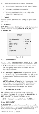
Page 17: ...istribution variations and non standard processing BLC Backlight Compensation compensates light to the object in the front to make it clear but may cause overexposure of the background where the light is strong WDR Wide Dynamic Range helps the camera provide clear images even under backlight circumstances WDR balances the brightness level of the whole image and provides clear images with details 3...

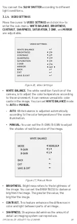
Page 18: ...ove unrealistic color casts in the image You can set WHITE BALANCE mode to AUTO or MANUAL AUTO White balance is adjusted automatically according to the color temperature of the scene illumination MANUAL You can set the R GAIN B GAIN to adjust the shades of red blue color of the image Figure 27 Manual Mode BRIGHTNESS Brightness refers to the brightness of the image You can set the BRIGHTNESS to dar...

Page 19: ...HT Under the SMART LIGHT sub menu you can set the mode to AUTO or OFF Figure 28 Smart Light AUTO Under the AUTO mode the white light turns on automatically when the environmental illumination becomes poor THRESHOLD value controls the sensitivity of the white light The greater the value the more sensitive the white light LEVEL value controls the white light brightness The greater the value the brig...

Page 20: ...s can be configured Figure 30 Motion 1 Select a MOTION area 2 Set the MODE as ON 3 Click the up down left right button to define the position and the size of the area DPC Defective Pixel Correction Defective pixels are pixels in a CMOS image sensor that fail to sense light levels correctly This series of cameras supports defective pixel correction You can set the DPC as ON or OFF 3 1 7 FACTORY DEF...

Reviews: