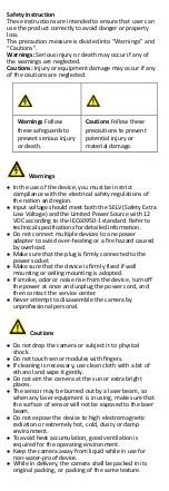
HIKVISION 2 MP Series User Manual Download Page 7


3


Menu Description 

Please follow the steps below to call the menu. 

NOTE: 

The menu description part is for your reference only. It 
might have some differences due to the specific model 
that you have. 
Steps: 
1.


Connect the camera with the TVI DVR, and the 

monitor, shown as the figure 3-1. 

Camera

TVI DVR

Monitor


Figure 3-1


Connection 

2.


Power on the camera, TVI DVR, and the monitor to 
view the image on the monitor. 

3.


Click PTZ Control to enter the PTZ Control interface. 

4.


Call the camera menu by clicking      button, or call 
preset No. 95. 

EXPOSURE 

MODE

BLC

MAIN MENU

VIDEO 

SETTINGS

EXIT 

SAVE & EXIT

HLC

GLOBAL

CONTRAST

SHARPNESS

SATURATION

MIRROR

BACK

VIDEO 

FORMAT

FACTORY 

DEFAULT

BRIGHTNESS

EXIT

SAVE & EXIT 

DAY/NIGHT

BACK

EXIT

SAVE & EXIT

IR LIGHT

Smart IR

D->N THRESHOLD

N->D THRESHOLD

IMAGE MODE

MODE

DWDR

AGC


Figure 3-2


Main Menu Overview 

5.


Click the direction arrow to control the camera. 
1)


Click up/down direction button to select the 
item. 

2)


Click Iris + to confirm the selection. 

Summary of Contents for 2 MP Series

Page 1: ...ealer This manual applies to the models below Model DS 2CE70D0T ITMF This manual may contain several technical incorrect places or printing errors and the content is subject to change without notice T...

Page 2: ...his device must accept any interference received including interference that may cause undesired operation EU Conformity Statement This product and if applicable the supplied accessories too are marke...

Page 3: ...mounting is adopted If smoke odor or noise rise from the device turn off the power at once and unplug the power cord and then contact the service center Never attempt to disassemble the camera by unpr...

Page 4: ...able parameters Auto white balance Switchable TVI AHD CVI CVBS video output SMART IR 3 axis adjustment 1 2 Overview 1 2 1 Overview of the Camera DC12V IN Mounting Base Main Body Enclosure Stopper Scre...

Page 5: ...o secure the camera If the product does not function properly contact your dealer or the nearest service center DO NOT disassemble the camera for repair or maintenance by yourself 2 1 Installation of...

Page 6: ...xpansion bolts 6 Align the screw hole on the main body to the notch and press it Notch Figure 2 5 Align the screw hole to the Notch 7 Connect the corresponding cables 8 Power on the camera to check wh...

Page 7: ...he image on the monitor 3 Click PTZ Control to enter the PTZ Control interface 4 Call the camera menu by clicking button or call preset No 95 EXPOSURE MODE BLC MAIN MENU VIDEO SETTINGS EXIT SAVE EXIT...

Page 8: ...e brightness of the strong spots to improve the overall images DWDR Digital Wide Dynamic Range Digital wide dynamic range gives the camera the ability to view dark areas of the given image as well as...

Page 9: ...mera is N D THRESHOLD Night to Day Threshold Night to Day Threshold is used to control the sensitivity of switching the night mode to the day mode You can set the value from 1 to 9 The larger the valu...

Page 10: ...clarity of the image in poor light conditions The AGC level can be set as HIGH MEDIUM or LOW Note The noise will be amplified when setting the AGC level MIRROR OFF H V and HV are selectable for mirro...

Reviews: