


—
4
—
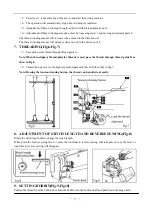
Hold the needle thread by hand,turn the pulley a circle by right hand.By pulling up the needle thread,the bobbin
thread will be lifted.Combination of bobbin thread and needle thread should be aligned and led back ward.
10.
ADJUSTMENT OF THREAD TENSION(Fig.11,Fig.12,Fig.13)
There is virtually no need to adjust the bobbin
thread tension, except for special kind of the
thread, when slight adjustment will be
necessary.
Turning the screw 1 clockwise will increase
the tension of lower thread, otherwise, the tension of lower thread will
decrease (Fig.12).
Needle thread tension should be adjusted in reference to bobbin
thread tension.The needle thread tension can be adjusted by thread
tension adjusting nut.
11.
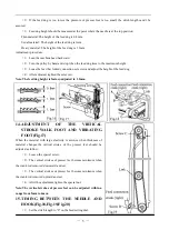
ADJUSTMENT OF THE PRESSURE OF
PRESSER FEET(Fig.14)
The pressure of the presser feet is regulated by the adjusting screw.
To increase the pressure, turn the screw to clockwise, and decrease it, turn the screw to counter-clockwise.
12.
TIMING BETWEEN THE HOOK AND NEEDLE(Fig.15)
(
1
)
Set the stitch length to “6”on the feed setting dial.
(
2
)
When the needle is lifted 2.4mm from the lower dead
point,the following positional relationship should be maintained:
a.The lower edge of needle eye should be 2.3mm below the
hook point.
b.The center of the needle the hook point is on a line.
c.Gap between the hook point and the side face of needle
should be 0.05mm.
13.
ADJUSTMENT OF THE HEIGHT OF
THE FEED DOG(Fig.16)
The height of the feed dog should be adjusted for different
materials:
(
1
)
If the feed dog is too high,or the pressure of presser foot
is too large,the materials will be damaged.
Summary of Contents for GC24698-BLHL
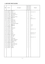
Page 9: ...A ARM BED MECHANISM 7 7 ...
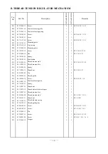
Page 11: ...B THREAD TENSION REGULATOR MECHANISM 9 9 ...
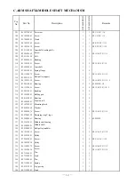
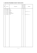
Page 13: ...C ARM SHAFT MIDDLE SHAFT MECHANISM 11 11 ...
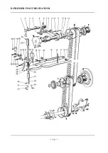
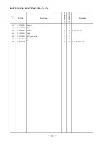
Page 16: ...D PRESSER FOOT MECHANISM 14 14 ...
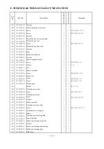
Page 19: ...E NEEDLE BAR THREAD TAKE UP MECHANISM 17 17 ...
Page 22: ...F STITCH REGULATOR MECHANISM 20 20 ...
Page 24: ...G LOWER SHAFT FEEDING SHAFT MECHANISM 22 22 ...
Page 27: ...H HOOK SADDLE MECHANISM 25 25 ...
Page 29: ...I OIL LUBRICATION MECHANISM 27 27 ...
Page 31: ...J ACCESSORIES 29 29 ...