background image

Fitting Instructions 

51305650

www.herthundbuss.com 4

Plug

Number of pins: 13
Voltage: 

24 V

1.  

Dismantle the multicore cable (piece 
no. 1) by about 30 mm, strip the insula-
tion of the single cores by 7mm and tin-
plate them.

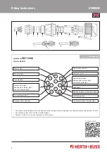
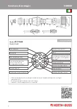
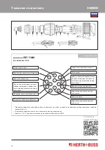
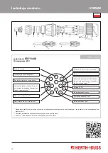
2.   Dismount the plug (pieces nos. 2–9) and 

slide the pieces nos. 2–5 on the cables in 
the represented order (see. Fig.).

3.   Loosen the contact screws for the poles 

required in order that the single cores 
can be entered into the pin insert (piece 
no. 8).

4.   Loosen both screws of the strain relief 

clip (piece no. 6). Remove the strain relief 
clip from the pin insert and slide it over 
the   cable.

5.   Plug the internal single cores nos. 1–4 

and tighten them by the contact screws.

6.  

Slide the insulation ring (piece no. 7) 
over the 4 internal single cores, put it on 
the pin insert and press it down until a 
lock is felt (Fig. A).

7.   Plug the external single cores nos. 5–13 

into the associated contacts and tighten 

them by the contact screws. By all means 
it must be ensured that each single core 
is entered into the contact bore com-
pletely.

8.   Centre the cables, position the strain re-

lief clip in the links of the pin insert and 
tighten them (Fig. B).

9.   Put the pin insert mounted so far into the 

frame (piece no. 9) of the pin insert. 


Attention! The coded position must be 
observed. Correct fit is possible only with 
one position.

10.  Then screw the cap (piece no. 5) to the 

frame of the pin insert and tighten it us-
ing a SW 36 open-end wrench. (A tight fit 
is reached when the screw is overturned).

11.   Attach the rubber bushing (piece no. 4) to 

the cap (piece no. 5). (A lubricant may be 
helpful.)

12.  Screw the nut (piece no. 2) with the slide 

ring (piece no. 3) tightly to the cap (piece 
no. 5)

Summary of Contents for ELPARTS 51305650

Page 1: ...ELPARTS Einbauhinweis Steckdose ...

Page 2: ...cken und ganz niederdrücken bis eine spürbare Verrastung erfolgt Abbil dung A 7 Äußere Einzeladern Nr 5 13 in zugehöri ge Kontakte stecken und Kontaktschrau ben festziehen Dabei ist unbedingt darauf zu achten dass jede Einzelader vollständig in die Kontaktbohrung einge führt wird 8 Kabel ausrichten Zugentlastungsschelle in den Stegen des Stifteinsatzes positio nieren und festziehen Abbildung B 9 D...

Page 3: ...tmals für andere Funktionen genutzt 3 Die Kontakte 11 und 12 sind nur bei einem ADR System angeschlossen Steuerung Anhängerbremse 2 Bremsleuchten Rechte Schlussleuchte Umriss leuchte Begrenzungsleuchte und Kennzeichenleuchte 1 Abfüllsicherung 3 Linke Schlussleuchte Umriss leuchte Begrenzungsleuchte und Kennzeichenleuchte 1 Armaturenschrankbeleuchtung 3 Nebelschlussleuchte Fahrtrichtungsanzeiger re...

Page 4: ... internal single cores put it on the pin insert and press it down until a lock is felt Fig A 7 Plug the external single cores nos 5 13 into the associated contacts and tighten them by the contact screws By all means it must be ensured that each single core is entered into the contact bore com pletely 8 Centre the cables position the strain re lief clip in the links of the pin insert and tighten th...

Page 5: ...today 3 Contacts 11 and 12 are only connected in an ADR system Trailer brake control 2 Stop lights Right hand taillight position light marker light and licence plate light 1 Overspill protection 3 Left hand taillight position light marker light and licence plate light 1 Fittings cabinet lighting 3 Rear fog light Right hand direction indicator light Axle lifting device Left hand direction indicator...

Page 6: ...r sur l insert mâle et l enfoncer jusqu à sentir l encliquetage illustration A 7 Insérer les fils individuels extérieurs n 5 à 13 dans les contacts correspondants et les fixer en serrant les vis de contact Il est important de veiller à ce que chaque fil individuel soit complètement inséré dans l alésage de contact 8 Aligner les câbles positionner le collier de décharge de traction dans les tiges d...

Page 7: ... d autres fonctions 3 Les contacts 11 et 12 sont raccordés uniquement dans le cas d un système ADR Commande du frein de la remorque 2 Feux stop Feu arrière feu de gabarit feu d encombrement et feu éclaireur de plaque côté droit1 Limiteur de remplissage 3 Feu arrière feu de gabarit feu d encombrement et feu éclaireur de plaque côté gauche1 Éclairage de l armoire à connexions 3 Feu antibrouillard ar...

Page 8: ... spina e spingerlo comple tamente verso il basso fino a quando non si blocca in modo percepibile figura A 7 Inserire i conduttori singoli esterni n 5 13 nei relativi contatti e serrare le viti di con tatto Fare assolutamente attenzione che ogni conduttore singolo sia inserito com pletamente nel foro di contatto 8 Allineare il cavo posizionare la fascet ta scarico della trazione nei traversini dell...

Page 9: ...ltre funzioni 3 I contatti 11 e 12 sono collegati solo in un sistema ADR Comando freno rimorchio 2 Luci posteriori di stop Luce di posizione posteriore destra luce perimetrale luci d ingombro e luce targa 1 Valvola di travaso 3 Luce di posizione posteriore sinistra luce perimetrale luci d ingombro e luce targa 1 Illuminazione armadio di comando 3 Retronebbia Indicatore di direzione destro Sollevam...

Page 10: ...jas y empujar ha cia abajo del todo hasta que se produzca un encastre audible Figura A 7 Änsertar los alambres individuales exteriores n 5 13 en los contactos correspondientes y apretar los tornillos de contacto Al hacerlo es imprescindible que tenga cuidado para que cada alam bre individual se introduzca del todo en el orificio de contacto 8 Orientar el cable posicionar la abrazade ra de descarga...

Page 11: ...con frecuencia actualmente para otras funciones 3 Los contactos 11 y 12 están conectados solo con un sistema ADR Control del freno de remolque 2 Luces de freno Luz trasera derecha lámpara de gálibo luz de posición y luz de la matrícula 1 Fusible de descarga 3 Luz trasera derecha lámpara de gálibo luz de posición y luz de la matrícula 1 Iluminación de los instrumentos 3 Luz trasera antiniebla Inter...

Page 12: ...7 через 4 внутренних жилы уста новите на штифтовую вставку и при жмите до ощутимой фиксации рису нок A 7 Вставьте внешние жилы 5 13 в соответ ствующие контакты и затяните контакт ные болты Учтите что каждую жилу необходимо полностью ввести в кон тактное отверстие 8 Выровняйте кабель расположите хо мут приспособления для уменьшения растягивающего усилия в перемычках штифтовой вставки и затяните рис...

Page 13: ...12 подключены только при использовании системы ADR Управление тормозом прицепа 2 Фонари сигнала торможения Правый задний габаритный огонь габаритный фонарь габаритные огни и фонарь освещения номер ного знака 1 Предохранитель переполнения 3 Левый задний габаритный огонь габаритный фонарь габаритные огни и фонарь освещения номер ного знака 1 Подсветка приборного шкафчика 3 Задний противотуманный фон...

Page 14: ...żyć na wkładkę męską i docisnąć aż na stąpi odczuwalne zatrzaśnięcie rys A 7 Umieścić zewnętrzne żyły nr 5 13 w od powiednich stykach i dokręcić za pomocą śrub stykowych Koniecznie należy przy tym zwrócić uwagę by każda żyła była w całości wprowadzona do otworu styko wego 8 Wyrównać przewód umie ścić opaskę kablową odciążają cą w przekładkach wkładki męskiej i docisnąć rys B 9 Zmontowaną w ten spo...

Page 15: ...y do innych funkcji 3 Styki 11 i 12 są podłączone tylko w przypadku systemu ADR Sterowanie hamulcem przyczepy 2 Światła STOP Prawa tylna lampa światło obryso we światła postojowe i oświetlenie tablicy rejestracyjnej 1 Ochrona przelewowa 3 Lewa tylna lampa światło obryso we światła postojowe i oświetlenie tablicy rejestracyjnej 1 Oświetlenie tablicy rozdzielczej 3 Tylna lampa przeciwmgłowa Kierunko...

Page 16: ...rzeugteile GmbH Co KG Dieselstraße 2 4 ı DE 63150 Heusenstamm Herth Buss France S A 270 Rue Col de La Chau ı FR 26300 Chateauneuf sur Isere Herth Buss Belgium Rue de Fisine 9 ı BG 5590 Achene KOF01474 ı Stand 03 2013 ...

Reviews: