

4
HermanMiller
Installation Instructions
1BN0MC rev A
FG159 - Data Box
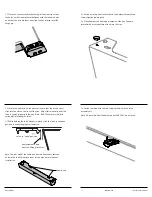
Step 1
1.1 Insert button head screws through holes in wire manager and
into nut plate.
1.2 Position wire manager up to underside of chase extrusion at
desired location. Engage nut plate inside chase groove by fully
inserting button head screw and turning until tight.
1.3 Position other side of Cable Management Sleeve up to
underside of the work surface at desired location. Use holes in
the hinge plate to mark hole locations. Drill pilot holes.
1.4 Secure hinge plate with pan head screws.
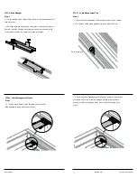
1.5 Unzip and remove the fabric cover.
1.6 Position wires over wire catch and along track.
1.7 Secure with velcro straps on track.
1.8 Wrap wires and track with sock. Zip wires and track inside
sock.
1.9 Velcro ends of sock over hinge housing.
Disassembly and Recycling:
Materials Identification and Segregation:
Where possible, plastic components are marked with ASTM recycling
codes. Use these codes to identify material type for recycling. Non
marked components should be treated as mixed plastic. Ferrous metals
can be identified using a small magnet for recycling. Non-ferrous metals
should be separated and recycled separately.
To disassemble product, reverse the above installation steps:
For more information about our products and services please visit us at
hermanmiller.com or call (800) 851 1196.
©2018 Herman Miller, Inc., Zeeland, Michigan Printed in U.S.A. Part No.
1BN0MC – A