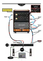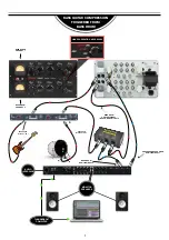
GETTING STARTED
4
FRONT
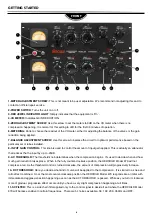
1-METER ADJUSTMENT SCREW:
This is not meant to be user adjustable. We recommend not adjusting this and to
contact an official repair service.
2-POWER SWITCH
: Turns the unit on or off.
3-RED JEWEL INDICATOR LIGHT
: Simply indicates that the equipment is ´On´.
4-VU METER:
Indicates GAIN REDUCTION.
5-ZERO ADJUSTMENT SCREW:
Use this screw to set the meters to 0dB on the VU meter when there is no
compression happening. It is normal for this setting to drift for the first 30 minutes of operation.
6-METERING:
Knob to choose the readout of the VU meter, either for adjusting the balance of the valves or the gain
reduction being applied.
7-BALANCE ADJUSTMENT SCREW:
Use this screw to balance the circuit for optimum performance based on the
particular set of tubes installed.
8- INPUT GAIN CONTROL:
This knob is used to control the amount of input gain applied. This is actually an attenuator
that reduces the the input by up to -20dB.
9- AC THRESHOLD:
The threshold knob determines when the compression begins. It’s used to decide when and how
much gain reduction takes place. When in the fully counter-clockwise position, the HERCHILD Model 670 will not
compress at all. As the threshold control is turned clockwise, the amount of compression will progressively increase.
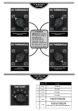
10- DC THRESHOLD:
Here you decide what kind of curve will be applied to the compression. It is similar to a knee and
ratio effect combined. So at the most counter-clockwise position the HERCHILD Model 670 responds like a limiter with
immediate and aggressive action happening as soon as the AC THRESHOLD is passed. While as you turn it clockwise
more of gradual, progressive effect occurs until you have a very slight compression happening at all times.
11-SC FILTER:
This is a side chain filter applied only to the control signal to decide if and where the HERCHILD Model
670 will be less sensitive to certain frequencies. There are 5 choices available: 50, 100, 200, 350Hz and OFF.
3
2
10
4
1
5
6
7
8
9
11
12
13


