4 • Service Manual — COATS Model IBS 2000
Direct Drive
Servicing
Service should be performed only by a factory trained
COATS
®
Service Technician. The troubleshooting and
service procedures in this manual are arranged to allow
rapid and thorough service. The steps are:
• Preliminary Inspection
• Functional Checks
• Repair Of Failure
• Replacement Or Adjustment
• Functional Checks
Identification of replacement parts required can be
accomplished by using the pictorial breakdown and index
in this manual. It is important that the FUNCTIONAL
CHECKS be performed IN SEQUENCE and the PROB-
LEM ISOLATED. If an adjustment is made, the entire
FUNCTIONAL CHECK must be performed SUCCESS-
FULLY before the balancer can be considered available
for service.
Equipment Needed
1.
AC / DC - Volt / Ohm meter (DVM).
2.
Test Wheel - Domestic 14" x 6" steel wheel with a
center hole suitable for mounting with a back cone. A
new 195/70/14 tire properly mounted and inflated, bal-
anced to within 0.02 ounces should be part of this wheel
assembly. The lateral run out of this wheel should be less
than 1/8". Modeling clay and 4 oz. test weight.
3.
Flat and Phillips screw drivers, and dead blow hammer.
4.
Tester for phone cables and jacks. (Modapt adaptor,
Contact East Part #118-785, call 1-800-225-5334 to order.)
5.
Thread locking anaerobic (Loctite 242 or equivalent).
Retaining compound (Loctite 601 or equivalent).
6.
Torque Wrench & a 5/16 X 6" hex socket for the
torque wrench.
7.
Small Allen wrenches, pot adjusting tools, & a 3/8"
nut driver.
8.
Chip extractor tool, Ammco part # 29977.
9.
A dial indicator (runout gauge) , Ammco part # 2850,
or 29752.
10.
Sockets: 3/8, 7/16, 3/4, 1/2, 9/16 inch, a speed han-
dle, or ratchet.
11
. A drill and 1/8" drill bits, pop rivet gun, and 1/8" rivets.
12.
A 7/16" - 3/8" box end wrench, and cutters for banding.
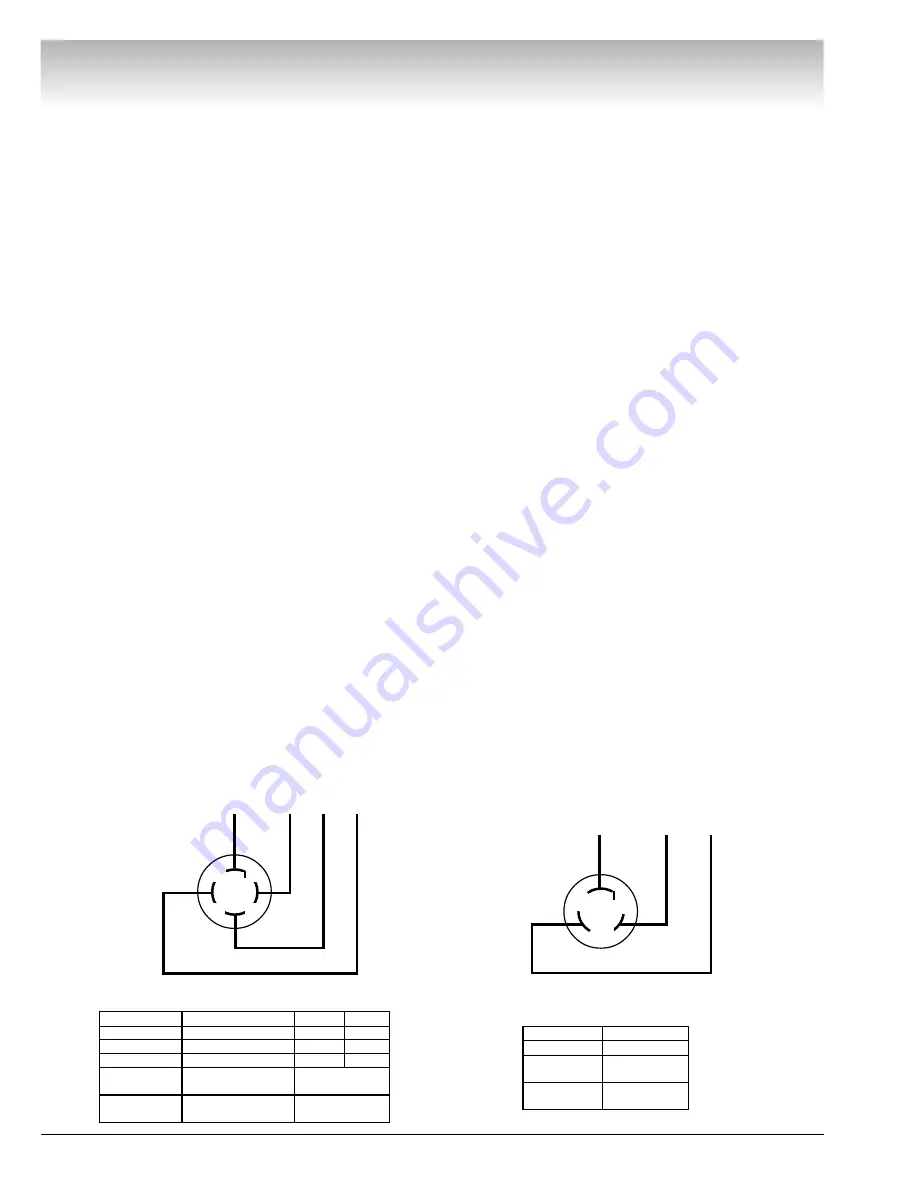
Voltage & Phase Checking Procedure
1.
Unplug the Balancer from the power source.
2.
Perform all voltage checks shown in the appropriate
diagram and chart at the power receptacle. If one or all
voltage measurements is faulty be sure to check the sta-
tus of the circuit breakers that supply the Balancer.
3.
Check from one of the power terminals to the
ground terminal to verify a ground is present. The voltage
measurement should be approximately one half of the
available voltage (i.e. 220V should read 110V).
Note: If any faults are found in the above pro-
cedure, it is the responsibility of the owner.
COATS
®
authorized service personnel are not
responsible for wiring within the building.
4.
Plug the balancer into a power source.
5.
Use an Ohmmeter to check the resistance between
the frame of the balancer and the building ground. The
resistance should be less than 1 ohm. If the resistance
measurement is greater that one (1) ohm, check the
power cord plug and frame connection for proper contact.
RED
WHITE
GREEN
GROUND
X
Y
Z
BLACK
GREEN
BLACK
RED
GROUND
A
B
THREE PHASE VOLTAGE REQUIREMENTS / INFORMATION
208V/220V/230V
380V
460V
X - Y
195-250
370-420
420-480
X - Z
195-250
370-420
420-480
Y - Z
195-250
370-420
420-480
Plug
Installed
Hubbell 2421
Hubbell 2431
Required
Hubbell 2420 or
Hubbell 2430 or
Mating Outlet
Equivalent
Equivalent
SINGLE PHASE VOLTAGE
REQUIREMENTS/ INFORMATION
208V/220V/230V
A - B
195 - 250
Plug
Hubbell
Installed
5466-C
Required
Hubbell 5462 or
Mating Outlet
Equivalent
Summary of Contents for Coats IBS 2000
Page 2: ...ii Service Manual COATS Model IBS 2000 Direct Drive...
Page 26: ...22 Service Manual COATS Model IBS 2000 Direct Drive Motor Controller Diagram...
Page 36: ...32 Service Manual COATS Model IBS 2000 Direct Drive IBS 2000 Wiring Diagrams...
Page 37: ...Service Manual COATS Model IBS 2000 33 Direct Drive...
Page 38: ...34 Service Manual COATS Model IBS 2000 Direct Drive...
Page 39: ...Service Manual COATS Model IBS 2000 35 Direct Drive...


