


16 • AMMCO 800 On-The-Vehicle Brake Lathe
On-The-Vehicle
10.4
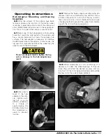
Turn the power switch OFF and disengage the
lock pin (yellow) from the runout adjustment head to
allow it to rotate with the lathe for the remainder of
the refinishing process.
Tool Holder Adjustment
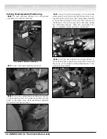
11.0
Turn the power switch ON, loosen both tool
holder locking levers located on top of the cutting
head assembly, and position the carbide inserts to
clear the brake rotor width.
11.1
Using the feed handwheel, position the car-
bide inserts inward onto the rotor surface, approxi-
mately 1/2-inch or the most worn area.
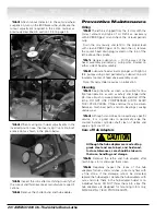
11.2
The cutting adjustment knobs are graduated
.002-inch per tick mark. Note that the adjustment from
number to number will move the carbide insert 0.004-
inch.
11.3
Turn the insert adjustment knob clockwise
bringing the carbide insert inward until a contact revolu-
tion is made with the rotor face. After the insert contacts
the rotor face, continue turning the insert adjustment
knob until a minimum cleanup depth is achieved. Note
the insert adjustment knob reading and then back the
knob off one counterclockwise revolution.
Adjust the opposite carbide insert in the same manner.


