


8 • AMMCO 800 On-The-Vehicle Brake Lathe
On-The-Vehicle
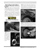
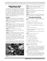
4.2
If adjustment is required, use the T-handle hex
wrench to position the tool holders.
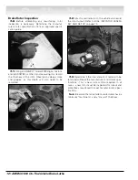
4.3
If the carbide inserts are damaged, rotate the
entire lathe upside down. This provides easy access to
replace or rotate the carbide inserts.
Note: Carbide inserts are mounted upside-down in
the insert holders.
Familiarize Yourself with the 800 Brake
Lathe
There are safety and shut down sys-
tems to aid in the performance of
good brake work. To understand
each system feature and recognize its con-
dition, we strongly recommend that you
complete the following sequential exer-
cise.
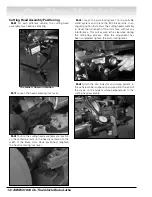
5.0
Connect to power using the twist-lock recepta-
cle and power cord. Note that when connecting the
power cord to the control box, the power switch lights
up indicating power is available to the control box from
a power source. Note the location of the ON/OFF
switch.
5.1
Note the various lights on the control box;
these indicate a lathe status.
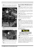
5.2
Before switching the power on, disengage the
runout adjustment head by pulling out the lock pin (yel-
low).
5.3
Switch the power ON; the runout adjustment
head rotates. Observe that the ADJUST RUNOUT
light status is now green on the control box.