background image

S320 User Guide 

PN 875-0281-000 Rev C2 

Chapter 2: Installation 


Ports and Connections 

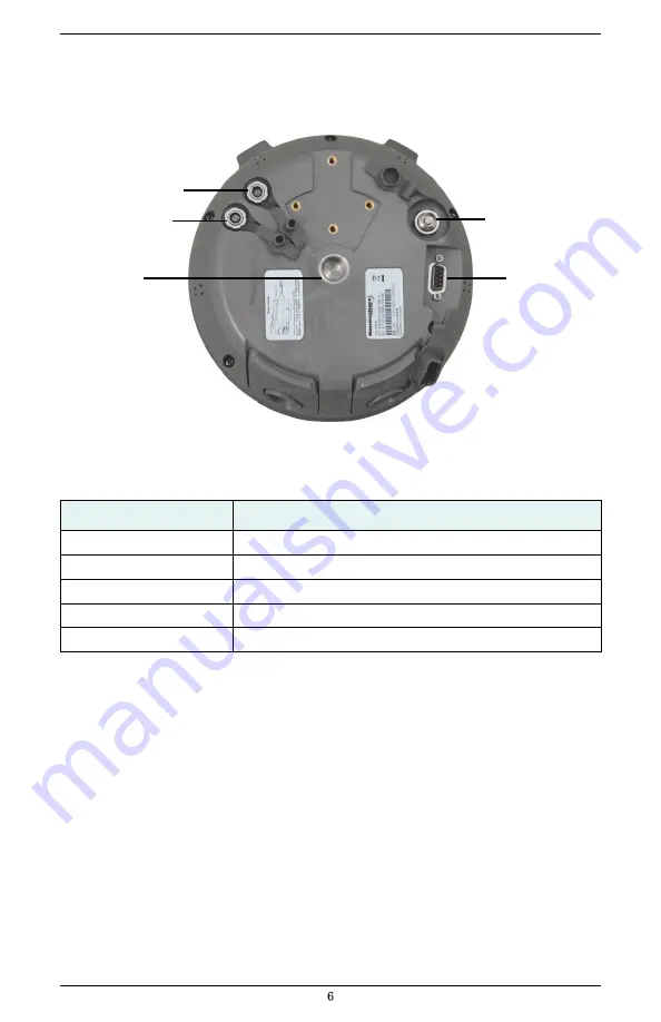
All connections and ports are located on the bottom of the unit, as shown in Figure 2-1. Table 
2-1 pr
ovides additional information about each port/connection. 


Data port 

Power port    


Antenna port 


Mounting hole    


Serial port 


Figure 2-1: S320 ports and connectors 


Table 2-1: S320 ports and connections 


Port 

What to connect 

Data port (ODU 9-pin) 

Data cable (Item H in Table 1-1 on page 3) 

Power port 

External power cable (Item F in Table 1-1 on page 3) 

Mounting hole 

Pole or tripod mount 

Antenna port 

External antenna (Item C in Table 1-1 on page 3) 

Serial port (DB9 female) 

External serial devices 

Summary of Contents for S320 GNSS

Page 1: ...S320 GNSS Survey Receiver User Guide Part No 875 0281 000 Rev C2 ...

Page 2: ... the radio to the frequency and power you are licensed to use at your location USA Federal Communication Commission FCC Radio frequency radiation exposure Information This equipment complies with FCC radiation exposure limits set forth for an uncontrolled environment GSM Mode When using the GSM to receive correction data this equipment should be installed and operated with a minimum distance of 20...

Page 3: ...hority to operate the equipment Caution Exposure to Radio Frequency Radiation This device must not be co located or operating in conjunction with any other antenna or transmitter Canada Industry Canada IC This device complies with RSS 210 of Industry Canada Operation is subject to the following two conditions 1 this device may not cause interference and 2 this device must accept any interference i...

Page 4: ... guide systems are covered by Patents No 6 539 303 and No 6 711 501 The Outback HitchTM automated hitch control system is covered by U S Patent No 6 631 916 The Outback eDriveTCTM GPS assisted steering system is covered by U S Patent No 7 142 956 Hemisphere GNSS products may be covered by one or more of the following U S Patents 6 111 549 6 397 147 6 469 663 6 501 346 6 539 303 6 549 091 6 631 916...

Page 5: ...he S320 On and Off 14 Modes of Operation 14 Displaying Current Module Status 15 Changing Module Status 16 Tilt Function Control 17 Alarm Buzzer 18 Power and Battery Status Charge 18 Replacing Swapping the Batteries 19 Removing Inserting the SD Card SIM Card 20 Bluetooth Communication 21 Upgrading S320 Firmware 22 Upgrading S320 Firmware via Serial Port 22 Upgrading S320 Firmware via SD Card 23 GSM...

Page 6: ...S320 User Guide PN 875 0281 000 Rev C2 Chapter 1 Introduction Product Overview and Features What s Included ...

Page 7: ...on and dual frequency Eclipse II OEM board the S320 is suitable for GIS mapping land surveying and construction with the following features Can be mounted on a range pole or tripod and carried by a single worker Small and lightweight with good pole balance Ruggedconstruction Hot swappablebatteries Datastorage Fully functional without the need for externalcables Radiocommunications If your S320 is ...

Page 8: ...79 000 400 MHz 804 0090 000 900 MHz B Antenna bracket for upward vertical antenna mounting 1 2 602 1096 000 C Antenna model type depends on region of use 1 2 150 0021 000 400 MHz 150 0022 000 900 MHz D SD card 1 2 750 1099 000 E Batteries rechargeable lithium ion 2 4 427 0043 000 F Power cable external 2 pin circular 3 m for base station unit N A 1 054 0119 000 G Battery charger 1 2 427 0044 000 H...

Page 9: ...er Guide PN 875 0281 000 Rev C2 Chapter 2 Installation Ports and Connections Installing Connecting the S320 Attaching the Antenna Connecting to a Power Source Connecting to External Device Setting Up the Unit ...

Page 10: ...connection Data port Power port Antenna port Mounting hole Serial port Figure 2 1 S320 ports and connectors Table 2 1 S320 ports and connections Port What to connect Data port ODU 9 pin Data cable Item H in Table 1 1 on page 3 Power port External power cable Item F in Table 1 1 on page 3 Mounting hole Pole or tripod mount Antenna port External antenna Item C in Table 1 1 on page 3 Serial port DB9 ...

Page 11: ... antenna inserted into bracket Figure 2 2 Antenna installation options Tip The antenna bracket offers an alternative solution in situations where installing the antenna on the bottom of the unit may not provide suitable reception such as where a small increase in antenna height has a noticeable effect on reception To install the antenna directly into the unit 1 On the bottom of the unit remove the...

Page 12: ...is 1 A at 12 VDC Note The power cable is included with the two unit base rover kit it is not included in the single unit kit See Table 1 1 on page 3 for information on the parts in each kit Power cable end Power port Figure 2 4 Connecting the power cable Note Applying external power does not charge the Li ion batteries in the battery trays You must use a suitable battery charger to charge the batt...

Page 13: ...le Table 2 4showsthe data port pinout specifications Table 2 4 Data port pinouts 1 9 center pin 3 7 Figure 2 6 Data port pinout assignment Note When using the USB device end of the included data cable Item H in Table 1 1 to connect to a USB port on an external device make sure the S320 is already powered on Pin Description 1 Not connected 2 Transmit data port TXD 3 Receive data port RXD 4 Data ter...

Page 14: ...nd gently remove the cable Setting Up the Unit Figure 2 7 shows a typical setup for both a base station unit and a rover unit tripod and pole mount not included data collector optional The antenna in Figure 2 7 is connected to the bottom of the unit you have the option of attaching the antenna to the antenna bracket so the antenna faces upward See Attaching the Antenna for more information on atta...

Page 15: ...eration Displaying Current Module Status Changing Module Status Tilt Function Control Alarm Buzzer Power and Battery Status Charge Replacing Swapping the Batteries Removing Inserting the SD Card SIM Card Bluetooth Communication Upgrading S320 Firmware GSM Functionality AT T 2G Network Configuring SMS Messaging Restoring Factory Defaults ...

Page 16: ... 1 S320 control panel The S320 beeps on any keypress Table 3 1 describes each button and LED on the control panel Table 3 1 S320 control panel items Diagram Item Name Description A Power button If unit is Off press and hold until unit powers up until you hear one beep If unit is On press and hold for approximately 3 seconds until you hear three beeps to turn unit off ...

Page 17: ...module 2 GPS position status LED Off noposition On yellow validposition Blink yellow operating as a base stationand converging on referencecoordinates 3 DGPS position status LED Off no differential corrections available On green differentially correctedposition computed 4 External power status LED Off external power notpresent On red external power present and inuse 5 and 6 Battery status LED Off ...

Page 18: ...wer up and the devices initialize Modes of Operation Table 3 2 lists the modes of operation for the S320 Table 3 2 S320 modes of operation Mode Description Eclipse Software GSM Mode UHF Mode Bluetooth Mode L band rover SBASRTKB OFF OFF ON or OFF Single point data collection for post processing SBASRTKB OFF OFF ON or OFF RTK Base Station SBASRTKB OFF ON ON or OFF RTK Rover UHF RTK OFF ON ON or OFF ...

Page 19: ...off or ON LED illuminated module powered on Table 3 3 illustrates the colors of the LEDs for each module Table 3 3 Module status LED color descriptions LED LED Color S320 Operation UHF GSM Off UHF radio and GSM module both off Green UHF radio on Yellow GSM module on GPS and DGPS position indicators Off both L band GPS Yellow DGPS None RTK rover GPS None DGPS Green RTK base GPS Yellow DGPS Green e ...

Page 20: ...f the module is off 2 Press the Selectbutton again to select the first module UHF GSM Note When you press the Select button the LED for the module status you are changing remains illuminated for 5 seconds during which time you can use the Power button to change the module status in step 3 3 If you want to change the current module s status press the Powerbutton Note When you press the Power button...

Page 21: ...control functionality is activated X axis tilt is displayedalong three horizontalLEDs Y axis tilt is displayed along three verticalLEDs Each LED shows a 0 5 tilt user configurable Table 3 4 illustrates the colors of the LEDs depending on the tilt direction of the unit These LED colors only apply if you have activated tilt control Table 3 4 Tilt control LED colors LED Colors Meaning Middle right ba...

Page 22: ...here is no external power the right battery is fully charged and the left battery is not present not in the unit Figure 3 2 No external power right battery full left battery not present Table 3 5 describes what the power battery LED colors indicate The S320 prioritizes power usage to use external power when available regardless of the status of the internal batteries Table 3 5 Power battery LED co...

Page 23: ...e them one at a time to ensure the unit is receiving power from at least one battery To replace swap a battery 1 For the battery you want to replace remove the battery tray by squeezing the thumb lever andpulling Thumb lever 2 Remove the battery from thetray 3 Insert the newbattery Note When inserting the battery make sure the end with the leads on top points away from the tray Battery leads 4 Rep...

Page 24: ...iate battery tray where the Left tray is labeled SD Right tray is labeled SIM To remove the SD card or SIM card 1 Remove the appropriate battery tray 2 Place the S320 upside down on its top to get a better view of thecard notch end goes in first Gently push the card in it will then snap back and slightly out Note When you insert either card make sure the contacts on the card are facing the top of ...

Page 25: ...h as a handheld data collector the following S320 Bluetooth information appears on the device HGPS S320 XXXXXX where XXXXXX is the Eclipse board serial number To complete the connection you must use the correct PIN Passkey which is 0000 Table 3 6 describes the Bluetooth status LED options Table 3 6 Bluetooth LED status LED Colors Meaning Off Bluetooth inactive Blue Active Bluetooth connection Blue...

Page 26: ...e for the most recent version from the Hemisphere GNSS website at www hemispheregnss com andsave it to your PC 2 Using the data cable included in your S320 kit connect the DB9 serial port end of the cable to your PC and connect the other end of the cable to the data port on the S320 seebelow To S320 data port To PC serial port Not used in this procedure 3 Power on the S320 4 Double click the Autol...

Page 27: ...ng the same folder structure of the contents on the SD card Remove the SD card from thePC If necessary remove the left battery tray from the S320 the left trayis labeled SD Insert the SD card into the S320 see Removing Inserting the SD Card SIM Card Replace the batterytray Power on the S320 The LEDs cycle from left to right while the receiver is readingthe upgrade file After the file has passed al...

Page 28: ...or in use with the S320 to a Wi Fi hotspot to gain access to a data network using the Data Collector Internet option in the Carlson SurvCE software In that case the user must have an external internet hotspot available created with a mobile phone GSM Overview Global System for Mobile Communications GSM is a network technology for mobile phone communications The GSM modem in the S320 is what allows...

Page 29: ...e CALG0 stream on igs ip net send the following command GSMCFG NRTIP www igs ip net 2101 CALG0 Usrnam passwd Configuring SMS Messaging The S320 supports Short Message Service SMS configuration and event updates for both base and rover operations When using SMS messaging keep the following in mind The GSM module must be powered on for SMS commands towork correctly Youcan send SMS messages to the S3...

Page 30: ...ers List To delete a number from the approved numbers list send the following command JSMS CONFIG 1 2 3 or keyword ALL DELETE For example to delete the number in slot 2 send the following command JSMS CONFIG 2 DELETE And to delete all numbers from the list send the following command JSMS CONFIG ALL DELETE Sending an SMS Message to an Approved Number To send an SMS message to an approved number sen...

Page 31: ...S320 User Guide PN 875 0281 000 Rev C2 Appendix A Troubleshooting ...

Page 32: ... Eclipse OEM board Verify the RCTM or the Bin messages are not being accidentally output send a JSHOW command Verify the baud rate settingsmatch Potentially the volume of data requested to be output could be higher than the current baud rate supports Try using a higher baud rate forcommunications No GNSS position Verify the antenna s view of the sky especially toward SBAS satellites south in the n...

Page 33: ...S320 User Guide PN 875 0281 000 Rev C2 Appendix B Technical Specifications ...

Page 34: ... band high precision services L band high precision service with GLONASS RTK formats CMR CMR 1 RTCM3 Update rate recording interval Selectable from 1 2 4 5 10 Hz 20 Hz available Static performance Horizontal 5 mm 0 5 ppm Cold start time 60 s typical no almanac or RTC Table B 2 Performance specifications Item Specification Static performance Horizontal 5 mm 0 5 ppm DGPS performance 0 3 m Table B 3 ...

Page 35: ...erature 30 C to 65 C 22 F to 149 F Storage temperature 40 C to 85 C 40 F to 185 F Humidity Up to 100 condensing Enclosure IP67 Shock EP455 2 m 6 56 ft pole drop Table B 6 Power specifications Item Specification Battery 2 x lithium ion 2 6 Ah each 5 2 Ah total 7 2 V External voltage 9 to 20 VDC Internal radio power 1 Watt Table B 7 Mechanical specifications Item Description Dimensions 114 H x 197 D...

Page 36: ... hole 6 control panel overview 12 power button 12 Select button 13 D data cable 3 22 data port 6 device name for Bluetooth 21 DGPS position status LED 13 displaying current module status 15 SMS approved numbers 25 E Eclipse II 2 environmental specifications 31 External power status LED 13 F features 2 firmware upgrading 22 G GNSS receiver specifications 30 GPS position status LED 13 GSM configurin...

Page 37: ...over GSM mode 14 RTK rover UHF mode 14 S SD card 3 inserting 20 removing 20 upgrading firmware 23 SD logging status LED 13 Select button 13 sending SMS message to approved number 26 serial port 6 upgrading firmware 22 setting up the S320 10 SIM card inserting 20 removing 20 Single point mode 14 SMS messaging 25 adding a number to approved list 25 deleting number from approved list 26 displaying ap...

Page 38: ...subject to this Agreement Hemisphere reserves the right to modify the Product without any obligation to notify supply or install any improvements or alterations to existing Software SUPPORT Hemisphere may make available directly or through its authorized dealers telephone and email support for the Software Contact Hemisphere to find the authorized dealer near you As well Hemisphere may make availa...

Page 39: ...HER LEGAL THEORY AND WILL SURVIVE A FUNDAMENTAL BREACH LIMITS ON LIMITATION OF LIABILITY Some jurisdictions do not allow for the limitation or exclusion of liability for incidental or consequential damages so the above limitation or exclusion may not apply to Licensee and Licensee may also have other legal rights which may vary from jurisdiction to jurisdiction BASIS OF BARGAIN Licensee agrees and...

Page 40: ...form or any delay in performance due to unforeseeable circumstances beyond its reasonable control such as labor disputes strikes lockouts war riot insurrection epidemic Internet virus attack Internet failure supplier failure act of God or governmental action not the fault of the non performing party FORUM FOR DISPUTES The parties agree that the courts located in Calgary Alberta Canada and the cour...

Page 41: ...or accuracy of any Product HEMISPHERE IS NOT RESPONSIBLE FOR PURCHASER S NEGLIGENCE OR UNAUTHORIZED USES OF THE PRODUCT IN NO EVENT SHALL Hemisphere GNSS BE IN ANY WAY RESPONSIBLE FOR ANY DAMAGES RESULTING FROM PURCHASER S OWN NEGLIGENCE OR FROM OPERATION OF THE PRODUCT IN ANY WAY OTHER THAN AS SPECIFIED IN Hemisphere GNSS s RELEVANT USER S MANUAL AND SPECIFICATIONS Hemisphere GNSS is NOT RESPONSI...

Page 42: ...8515 E Anderson Drive Scottsdale AZ 85255 USA Phone 1 480 348 6380 Fax 1 480 270 5070 precision hemispheregnss com www hemispheregnss com ...

Page 43: ...guration Management Coordinator Quality Assurance Michael Polinko Quality Assurance Manager DOCUMENT REVISION HISTORY Revision Date MM DD YY Author Change Description C2 04 21 17 R Stankovic User Guide updated to add references and warnings for 2G modem integration Record of Approvals Art Escobedo Approve 04 21 17 01 08 PM Rodrigo Leandro Approve 04 18 17 02 32 PM Lyle Geck Approve 04 19 17 01 26 ...

Reviews: