FIRST ENSURE THE POWER IS OFF at the main circuit breaker, and then test the wires
with a probe or multimeter to verify.
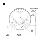
Insert the wires to the correct HE-HLS01 terminals by inserting a small Phillips-head
screwdriver into the slot beneath each terminal and unscrew to open.
Follow connection diagrams on Figure 1 or 2 or 3 and the instructions below:
• Power wires:
For AC power (85-265VAC) connect Line & Neutral lead wires to L & N
terminals labeled “IN”. For DC power (24-48VDC) connect “+” wire to terminal N and “–”
wire to terminal L.
• Load wires:
Connect Line & Neutral wires to L & N terminals labeled with “heating
element” graphic .
Note:
It is possibly to connect Neutral wire from load directly to your neutral line
(Figure 2).
Note:
HELTUN recommends installing cord terminals (electric wire ferrules) on the ends
of wires before connecting them to the HE-HLS01 outputs (various colors terminals are
included).
Note:
Zero-Cross technology is unavailable if the device is DC (24-48VDC) powered.
Tighten wires using Phillips screwdriver in slot beneath each wire.
If using the HE-HLS01 for radiant floor heating, connect the NTC temperature sensor
wire to the terminals labeled “NTC.” A 10 kΩ NTC sensor is included inside the HE-HLS01
packaging, but any NTC sensor can be used.
Note:
If an NTC sensor other than 10 kΩ is used, you must change the sensor resistance
value in the settings menu (Parameter 10).
If you will be using an external device to select modes for the HE-HLS01 (such as a
security system or wall switch), connect wires from the external device’s dry contacts to
the two HE-HLS01 terminals labeled “S1” & “Sx”.
Two different connection methods for external control are possible: (see Figures 1 & 2).
Note:
In case of using Figure 2 or 3, it is MANDATORY to connect S1 terminal to the
same wire connected to terminal N on the device (labeled as “IN”) through dry contacts
of an external device.
Switch On the main power at the circuit breaker. The HE-HLS01 will start up with the
original default factory settings and the LED indicator will blink red slowly meaning the
device is excluded from a Z-Wave network.
1.
2.
3.
4.
5.
INSTALLATION
The HELTUN HE-HLS01 High Load Switch must be installed by a licensed electrician in a
manner that conforms to local regulations and building codes. Provide these instructions
to the licensed electrician who is installing the HE-HLS01.
WARNING: Electrical power must be switched off during installation.
7
Summary of Contents for HE-HLS01
Page 1: ...QUICK START GUIDE High Load Switch HE HLS01...
Page 4: ...1...
Page 5: ...2...
Page 6: ...3...
Page 7: ...4...


