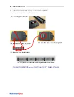
.
3
3.The third stage is to install the cables between the cassettes.
Start by ensuring the cable is correct ie, both performance and length
see the legend on the cable
.
Run the cable along the pre-planned route;
ensure that the cable do not
catch or snag against any sharp edges or bent around tight corners.
Do not pull the cable by MTP connector or boot as this can damage the
connector and prevent the cable from working.
The bend radius of the cable should be no less than 20x the outside
diameter of cable during the installation process.
Only when the cable is ready to installed into the rear of the cassette
should the dust cap from both the cable and adaptor located in the rear
of the cassette be removed.
Only mate one cable at a time
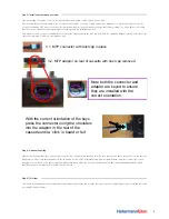
3.1. MTP connector with dust cap in place
3.2. MTP adaptor on rear of cassette with dust cap removed
Note both the connector and
adaptor are keyed to ensure
they are installed with the
correct orientation.
With the correct orientation of the keys
press the connector
using the shoulders
into the adaptor in the rear of the
cassette until a ‘click’ is heard or felt
Step 3: Install cable between cassettes
Start by ensuring the cable is correct ie, both performance and length see the legend on the cable.
Run the cable along the pre-planned route; ensure that the cable do not catch or snag against any sharp edges or bent around tight corners. Do
not pull the cable by MTP connector or boot as this can damage the connector and prevent the cable from working. The bend radius of the cable
should be no less than 20x the outside diameter of cable during the installation process.
Only when the cable is ready to installed into the rear of the cassette should the dust cap from both the cable and adaptor located in the rear of the
cassette be removed. Only mate one cable at a time
Step 4: Optional Labeling
Other actions to undertake are to label the ports on the front, there are two labelling fields for each cassette one above and one below the cassette.
Alpha Label is a free software available from the download section of the HellermannTyton website (www.htdata.co.uk) this contains the correct
template for the windows. The panel is supplied blank white labels which can be used instead of printed labels and magnifying windows which
should be snapped into place when the label has been fitted.
Step 5: Test links
This should be undertaken in the normal way for a permanent link taking into account the correct number of mated pairs/ connectors and the cable
test equipments procedures.


