BD0059V0002EN0416SO 460 985-52 / 04.16
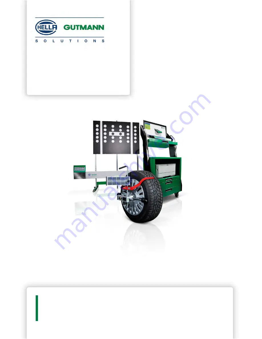
Operating Instructions
en
CSC-Kit Radar I
Page 1: ...BD0059V0002EN0416SO 460 985 52 04 16 Operating Instructions en CSC Kit Radar I...
Page 2: ...ions for the Electromagnet 4 2 Product Description 5 2 1 Intended Use 5 2 2 Delivery contents 5 2 3 Tool Description 7 3 Working with the CSC Kit Radar I 10 3 1 Precondition for the Use of the CSC Kit...
Page 3: ...ecautions must also be followed Furthermore all general requirements and standards of supervisory bodies trade associations and vehicle manufacturers as well as all laws regulations and codes of condu...
Page 4: ...ors or windows Never look directly into the laser beam Ensure proper room illumination Avoid trip hazards Secure mechanical parts from falling over or becoming loose 1 5 Safety Precautions for the Ele...
Page 5: ...re in connection with a diagnostic tool of Hella Gutmann you are able to calibrate e g the radar sensor or the camera for adaptive headlights The CSC Kit Radar I can be exclusively operated in combina...
Page 6: ...2005 4 Binding head screws 1 CSC Kit Radar II optional Mirror adjustment device with vacuum bell optional 1 CSC Kit Radar II optional Manual vacuum pump with vacuum hose optional 1 CSC Kit Radar II o...
Page 7: ...ld you identify any damage to the package then open the package in the presence of the delivery service and check the CSC Kit Radar I for hidden damage Any transport damage to the package supplied and...
Page 8: ...ached to the cross member 4 Attachment positions 1 2 and 3 Depending on the vehicle manufacturer a variety of attachment positions must be observed here They are described 2 3 2 Magnetic Laser Designa...
Page 9: ...attached in the exact horizontal position 2 3 3 Replacing the Batteries Replacing the Type AA Batteries Proceed as follows to replace the batteries 1 Switch off the laser beam 1 with the switch 2 2 Re...
Page 10: ...ehicle system is working properly No trouble codes stored in the ECU Possible vehicle specific preparations done Rear axle track adjusted properly Horizontal position of the vehicle on even surface en...
Page 11: ...ar adjustment plate 1 to the cross member as shown in the tool The angular adjustment plate must be within the radar sensor area The level gauge bubble must be centered 6 Follow the on screen instruct...
Page 12: ...op when fixing it to the cross member and may cause injuries Ask a second person to fix the angular adjustment plate to the cross member 4 Attach the angular adjustment plate 1 to the cross member in...
Page 13: ...lectromagnet is activated and the magnetic laser can be fixed onto the angular adjustment plate CAUTION Laser radiation Damage to destruction of the retina Never look directly into the laser beam 7 Sw...
Page 14: ...netic laser 10 Direct the horizontal and vertical level gauge 6 by shifting the magnetic laser The radar sensor can be calibrated if the horizontal and vertical level gauge bubbles are centered 11 Obs...
Page 15: ...ompliance with directive 2012 19 EU of the European Parliament and Council dated 04 Juli 2012 relating to Waste Electrical and Electronic Equipment WEEE and the German national statute governing the d...
Page 16: ...ed batteries into household waste but dispose of them properly The batteries can also be sent to Hella Gutmann for disposal free of charge 4 3 Technical Data of the Magnetic Laser 4 3 1 General Data A...
Page 17: ...CSC Kit Radar I General Information Technical Data of the Magnetic Laser Class 2 Operating range 5 m 17...
Page 18: ...Notes CSC Kit Radar I Notes 18...
Page 19: ...CSC Kit Radar I Notes Notes 19...
Page 20: ...IONS GMBH Am Krebsbach 2 79241 Ihringen GERMANY Phone 49 7668 9900 0 Fax 49 7668 9900 3999 info hella gutmann com www hella gutmann com 2016 HELLA GUTMANN SOLUTIONS GMBH 1 STUECK PIECE S 9XQ 460 985 5...