Temperature Control System WHS HE
Installation and Operating Instructions
12
EN
EN
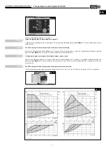
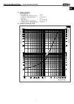
2�9 Calculation of the operating point
In connection with a Helios hot water heating element WHR.., the following guide values for the differential pressure
setpoint are approximated:
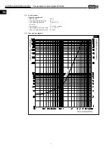
- Technical Data
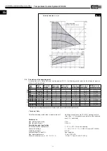
velocity constant I, II, III
Fig� 16
* The pressure loss in the piping depends on the pipe length, pipe diameter and the water flow rate!
Type
WHR
Water
volume
Line cross-
section
Press� loss
WHR [kPa]
Press� loss*
pipe [kPa]
Press� loss
WHSH [kPa]
Press� loss
total [kPa]
Different� press�
setpoint pump
250
470 l/h
3/4”
8
8
3.5
19.5
2.0 m
315
810 l/h
3/4”
9
8
4.5
21.5
2.2 m
355
1080 l/h
3/4”
9
10
5.5
24.5
2.5 m
400
1060 l/h
3/4”
11
10
5.5
26.5
2.7 m
2/40/20
610 l/h
3/4”
10
8
4
22
2.2 m
4/40/20
980 l/h
3/4”
7
10
5
22
2.2 m
2/50/25-30
1050 l/h
3/4”
7
10
5.5
22.5
2.5 m
4/50/25-30
1680 l/h
1”
5
8
12
25
2.5 m
1420 l/h
1”
8
8
9
25
2.2 m
4/60/30-35
2270 l/h
1”
7
10
20
37
3.7 m
2/70/40
2200 l/h
1”
6
10
20
36
3.6 m
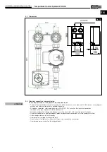
Duct
Pipe
Permitted pumping media (other media on request)
Heating water (pursuant to VDI 2035) water-glycol mix-
tures (max. 1:1; the performance data must be reviewed
over 20 % admixture)
Performance
Max. delivery head (Hmax)
6,0 m
Max. flow rate (Qmax)
3,6 m
3
/h
Permitted range of application
Installation location requirements
5 - 50°C < 90% RH non-condensing
Connection voltage
1 ~ 230 V +10 %/ -15 %, 50/60 Hz (as per IEC 60038)
Protection category
IP X4D
Energy efficiency index EEI
See type plate
Max. operating pressure
10 bar (1000 kPa)
Minimum inlet pressure at +95 °C/+110 °C
0.5 bar/ 1.0 bar (50 kPa/ 100 kPa)


