


EN
EN
Casing type ELS-GU
Installation and Operating Instructions
14
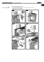
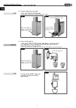
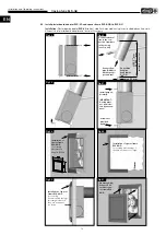
4�12 Connecting duct (Aluflex ducting)
Observe bending radius R
>
DN of the connection cable!
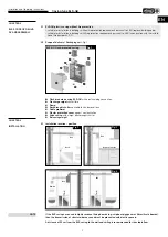
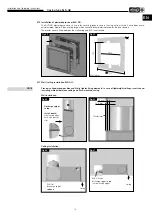
4�13 Connection cable
Cut circular grommet according to relevant electrical supply line or ductwork� IP protection is only achieved
when the cable grommet is air-tight with the cable or ductwork inserted!
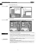
The connection cable must be stored so that water cannot penetrate along the cable in case of water expo
sure� The cable must not pass over sharp edges!
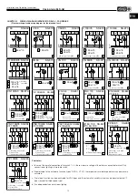
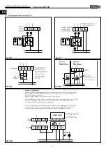
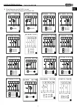
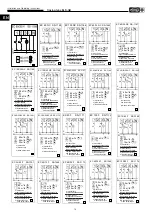
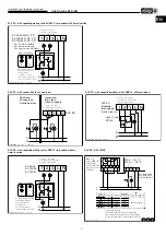
The electrical connection must be isolated from the mains power supply until final assembly!
The relevant standards, safety regulations (e.g. DIN VDE 0100) and the technical connection regulations of the energy
supply companies must be observed. An all-pole mains switch/isolator, with at least a 3 mm contact opening (VDE
0700 T1 7.12.2 / EN 60335-1) is mandatory. The rated voltage and frequency must be consistent with the information
on the type plate.
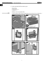
The accessory parts and installation and operating instructions must be placed in the ELS casing and closed
away with the cleaning protection cover when assembly is complete!
EMC regulation/standard
Important note for the electromagnetic compatibility
The interference resistance according to DIN EN 55014-2 depends on impulse form and energy share 1000 V to 4000
V. In case of operation with fluorescent tubes, switching power supplies, electronically controlled halogen lamps, etc.,
these values may be exceeded. In this case, additional anti-interference measures on-site are required (L, C or RC
modules, protective diodes, varistors).
NOTE
Fig�49
Bending radius R > DN
Fig�48
Connect steel/steel-
flex ducting (DN 80)
to discharge spigot
and attach with flexib-
le tape.
NOTE
Fig�50
100 mm
Grommet
6 mm
10 mm
Fig�51
100 mm
Grommet
6 mm
10 mm
DANGER
m
IMPORTANT NOTE


