background image

4

Electrical pre-heater AIR1-EVH RH

Installation and Operating Instructions

+40 °C). Damages due to improper transportation, storage or commissioning must be verified and are not liable for 
warranty.

2 .0 .3 Shipping

The shipping must be carried out carefully. It is recommended to leave the unit in the original packaging until installation 
to avoid possible damages and contamination. 
The shipping must be carried out by trained and experienced personnel and the necessary safety precautions should 
be taken to prevent overturning and slipping of the device. it should be ensured that the weight is evenly distributed 
when shipping the unit.

m

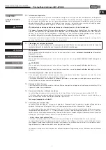
 Personal injury and/or material damage due to incorrect shipping!

It must be ensured that the means of transport/lifting is suitable to accommodate to the required weight and size 
capacity.
– Make sure that the unit is firmly seated before lifting it.

Material damage due to excessive load!

Before off-loading the units, please ensure that the means of transport/lifting have sufficient capacity for the required 
weight.

Risk of personal injury and material damage!

The package units may have an eccentric centre of gravity . If the package unit is incorrectly lifted, it can tip 
over . Falling or tipping package units can cause serious personal injury .
When lifting, the centre of gravity of the package unit must be vertically beneath the crane hook .

2 .0 .4 Disassembly and re-assembly

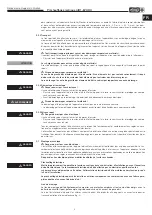
Danger to life due to electric shock!

An electric shock can result in death or serious injury.
– Ensure that the unit is voltage-free and isolated from the mains power supply. Ground and short circuit the unit, shield 

neighbouring live components.

– The unit must be isolated from the mains power supply before disassembly or re-assembly.

Risk of personal injury and material damage!

The disassembly and re-assembly of the unit are not part of routine maintenance.
– The disassembly and re-assembly of the unit may only be carried out by qualified specialist personnel.

Risk of material damage when installing heating and cooling registers!

The following must be taken into account when installing heating and cooling registers:
– Close all hydraulic stop valves.
– Isolate all connections and ensure that the unit is leak-free with regard to oil and refrigerants.
– Since the diameter of the heating and cooling pipes is small, water may remain in the register after emptying. For 

safety reasons, compressed air should be blown through the system to remove the remaining water.

2 .0 .5 Disposal

Danger to life due to electric shock

!

An electric shock can result in death or serious injury.
– Ensure that the unit is voltage-free and isolated from the mains power supply. Ground and short circuit the unit, shield 

neighbouring live components.

Dispose of all components and filters and disused operating materials (e.g. refrigerants) in an environmentally-friendly 
manner in accordance with the local codes, practices and environmental regulations.
An authorised specialist waste processing company must dispose of the unit or the individual components. The appo-
inted contractor must ensure that the components are separated according to material types.

2 .1  Mechanical assembly

m

 Danger to life due to electric shock!

The installation and connection of the unit may only be carried out by qualified specialist personnel. The electrical con-
nections must be carried out by a person who has proper professional training and experience in the relevant accident 
prevention regulations, as well as other generally recognised safety and occupational health codes, with authorisation 
to perform work on the unit.

Risk of injury due to electric shock, moving parts (fans) and hot surfaces .


Electrical pre-heater
The unit must be fully isolated from the mains power supply before all maintenance and installation work and 
opening the terminal compartment! The electrical connections must be carried out in accordance with the fol-
lowing wiring diagrams and must only be carried out by qualified electricians . The electrical connection must 
be fully isolated until the final assembly!
The electrical pre-heater is only suitable for installation outside in combination with the matching weather pro-
tection cover and an outside air intake hood!

Assembly area

The assembly position must ensure protection against reaching into the heating register. E.g. this is possible using 
ducts or the outside air intake hood.

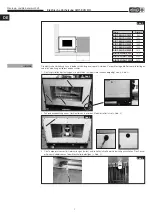
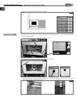
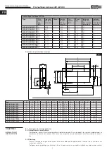
When installing the unit, the following criteria must be observed when installing the unit to ensure easy accessibility for
maintenance and maintenance work (Fig. 2).

DANGER

ATTENTION


DANGER

DANGER

WARNING

ATTENTION


DANGER

DANGER

DANGER


EN

Summary of Contents for AIR1-EVH RH

Page 1: ...chauffage lectrique AIR1 EVH RH f r AIR1 RH L ftungsger te for AIR1 RH ventilation units pour les centrales AIR1 RH DE EN FR Helios Ventilatoren MONTAGE UND BETRIEBSVORSCHRIFT INSTALLATION AND OPERATI...

Page 2: ...schreibung Seite 2 KAPITEL 2 INSTALLATION UND INBETRIEBNAHME Seite 3 2 0 Allgemeine Montagehinweise Seite 3 2 0 1 Sendungsannahme Seite 3 2 0 2 Einlagerung Seite 3 2 0 3 Transport Seite 4 2 0 4 Demont...

Page 3: ...ss Wenn die nachfolgenden Ausf hrungen nicht beachtet werden entf llt die Gew hrleistung Gleiches gilt f r Haftungs anspr che an den Hersteller Der Gebrauch von Zubeh rteilen die nicht von Helios empf...

Page 4: ...15000 22 31 75 3 400 50 190 31 54 100 max 80 400 max E I K T W R X U S V 110 B O C M8 P Ma e mm Art Nr Type B C E I K O P R S T U V W X 01262 AIR1 EVH RH 1500 520 760 700 200 173 380 265 378 338 350 3...

Page 5: ...rtung Die Demontage und der Wiederaufbau des Ger ts d rfen nur von qualifiziertem Fachpersonal durchgef hrt werden 2 0 5 Entsorgung m Lebensgefahr durch Stromschlag Ein Stromschlag kann zu Tod oder sc...

Page 6: ...ird s Abb 3 2 Schraubenabdeckungen am Ger t entfernen bevor das Modul installiert wird s Abb 4 3 Den Temperatursensor im Lieferumfang enthalten an die Au enluftseite der Vorheizung anschlie en Den Sen...

Page 7: ...ng montieren AIR1 Ger t wie folgt mit der Vorheizung verbinden s Abb 8 7 Abdeckung des Hauptschalters ffnen Leitungsquerschnitt der f r den Stromanschluss verwendet wird festlegen Die Leitung an die e...

Page 8: ...Kapitel der Montage und Betriebsvorschrift des jeweiligen AIR1 L ftungsger ts beachten 3 0 Service und Wartung Reinigungs und Wartungsarbeiten d rfen nur von einer Elektrofachkraft durchgef hrt werde...

Page 9: ...lter nach oben dr cken um eine manuelle R ckstellung zu erzielen Abb 12 Manuelle R ckstellung Die manuelle R ckstelltemperatur ist 90 C Wenn die Sicherheitstemperatur 90 C erreicht ist wird der Sicher...

Page 10: ...ption Page 2 CHAPTER 2 INSTALLATION AND COMMISSIONING Page 3 2 0 General installation instructions Page 3 2 0 1 Receipt Page 3 2 0 2 Storage Page 3 2 0 3 Shipping Page 4 2 0 4 Disassembly and re assem...

Page 11: ...ch can result in material damage if the safety instruction is not followed 1 2 Warranty claims Exclusion of liability If the preceding instructions are not observed all warranty claims shall be exclud...

Page 12: ...31 54 100 max 80 400 max E I K T W R X U S V 110 B O C M8 P Ma e mm Art Nr Type B C E I K O P R S T U V W X 01262 AIR1 EVH RH 1500 520 760 700 200 173 380 265 378 338 350 310 01710 AIR1 EVH RH 2000 58...

Page 13: ...t is leak free with regard to oil and refrigerants Since the diameter of the heating and cooling pipes is small water may remain in the register after emptying For safety reasons compressed air should...

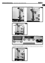
Page 14: ...module joins the unit see Fig 3 2 Remove screw covers on the unit before installing the module see Fig 4 3 Connect the temperature sensor included in delivery to the outdoor side of the pre heater Fa...

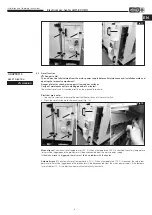
Page 15: ...metal parts to the pre heater Connect AIR1 unit to the pre heater as follows see Fig 8 7 Open main switch cover Check cable thickness for the power connection Connect the cables to the terminals and...

Page 16: ...g assistant For this purpose please refer to corresponding chapter in the installation and operating instructions for the respective AIR1 ventilation unit 3 0 Service and maintenance Cleaning and main...

Page 17: ...to access the reset switch 2 Press the reset switch up for a manual reset Fig 12 Manual reset The manual reset temperature is 90 C When a temperature of 90 C is reached the safety temperature limiter...

Page 18: ...e 2 CHAPITRE 2 INSTALLATION ET MISE EN SERVICE Page 3 2 0 Consignes de montage g n rales Page 3 2 0 1 R ception de la marchandise Page 3 2 0 2 Stockage Page 3 2 0 3 Transport Page 4 2 0 4 D montage et...

Page 19: ...e garantie R serves du constructeur Si les consignes figurant dans cette notice ne sont pas correctement respect es la garantie s annule Il en est de m me pour toute implication de responsabilit du fa...

Page 20: ...00 max 80 400 max E I K T W R X U S V 110 B O C M8 P Ma e mm Art Nr Type B C E I K O P R S T U V W X 01262 AIR1 EVH RH 1500 520 760 700 200 173 380 265 378 338 350 310 01710 AIR1 EVH RH 2000 580 860 7...

Page 21: ...de la maintenance courante Le d montage et le remontage de l appareil doivent exclusivement tre effectu s par un personnel qualifi 2 0 5 Mise au rebut m Danger de mort par choc lectrique Un choc lect...

Page 22: ...aux endroits o le module est accol la centrale voir fig 3 2 Retirer les cache vis de la centrale avant d installer le module voir fig 4 3 Raccorder la sonde de temp rature incluse dans la livraison du...

Page 23: ...centrale AIR1 au pr chauffage comme indiqu ci apr s voir fig 8 7 Ouvrir le couvercle de l interrupteur principal D terminer la section du c ble utiliser pour le raccordement raccorder le c ble la born...

Page 24: ...l assistant de mise en service Pour ce faire veuillez consulter le chapitre correspondant de la notice de montage et d utilisation de la centrale AIR1 concern e 3 0 Entretien et maintenance Les travau...

Page 25: ...Pousser le bouton de r initialisation vers le haut pour proc der la r initialisation manuelle voir fig 12 R initialisation manuelle la temp rature de r initialisation manuelle est de 90 C Lorsque cet...

Page 26: ...9 Pr chauffage lectrique AIR1 EVH RH Notice de montage et d utilisation...

Page 27: ...10 Pr chauffage lectrique AIR1 EVH RH Notice de montage et d utilisation...

Page 28: ...se 4 8112 Otelfingen GB HELIOS Ventilation Systems Ltd 5 Crown Gate Wyncolls Road Severalls Industrial Park A HELIOS Ventilatoren Postfach 854 Siemensstra e 15 6023 Innsbruck Colchester Essex CO4 9HZ...

Reviews: