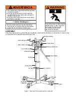
background image

OPERATION

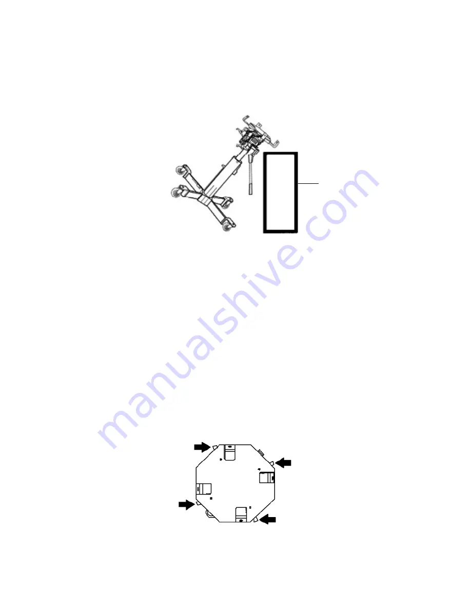
Priming Instructions (refer to Figure 2)

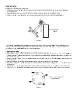
1. Tilt the entire tranmission jack over two casters so that the pump and handle are below the hydraulic cylinder as

shown in Figure 2.

2. Open the release valve knob "COUNTERCLOCKWISE" and pump handle until "resistance" is felt.
3. Close the release valve "clockwise" and continue pumping while restoring the jack to its upright position

The transmission saddle assembly is raised and lowered by means of an air operated stage and a hydraulic stage. A
locking pawl automatically engages at the end of the air cylinder travel to mechanically lock the cylinder and prevent
drop when the transmission is loaded onto the saddle assembly.

Transmission Removal

1. With vehicle elevated on lift, position the jack under transmission to be removed.
2. Connect 1/4" air nipple to air inlet port. Connect air hose to the air nipple. Depress the lift pedal that marked 

"UP"

 and

raise air stage to its fully extended position. The air stage will stop automatically by the locking pawl at its full height. Air
hose can be removed.

3. Close the release valve by turning the release valve knob in clockwise direction. Pump the handle until saddle reached

desired position

4. Make sure saddles are centered and positioned directly under the transmission to be removed.
5. Adjust the position of the saddle assembly side to side and tilt forward or backward to get a firm contact at the bottom of

transmission.

6. Slowly pump the handle with a small strokes so the saddle assembly raised slowly to contact with the transmission.
7. Push in the 4 ratchet brackets on saddle assembly firmly to grab the edges of transmission housing. (see Figure 3)


Figure 2

Unlock pawls to pull out

ratchet brackets.

Figure 3

Supporting

Station

Summary of Contents for HW93720

Page 1: ...Operating Instructions Parts Manual Model Number Capacity HW93720 1 2 Ton Telescopic Transmission Jack Made in the USA ...

Page 2: ... USE 1 Verify that the product and the application are compatible if in doubt call Hein Werner Technical Service 816 891 6390 2 Read the operator s manual completely and familiarize yourself thoroughly with the product its components and recog nize the potential hazards associated with its use before using this product SPECIFICATIONS Model Capacity Min Height Max Height Lifting Head Size Forward T...

Page 3: ...operates before attempting to use ADVERTENCIA Figure 1 Telescopic Transmission Jack Components Be sure all tools and personnel are clear before lowering load Only attachments and or adapters supplied by the manufacturer shall be used Safety Messages To avoid crushing and related injuries NEVER work on under or around a load supported only by a jack Immediately transfer load to appropriate work sta...

Page 4: ... to be removed 2 Connect 1 4 air nipple to air inlet port Connect air hose to the air nipple Depress the lift pedal that marked UP and raise air stage to its fully extended position The air stage will stop automatically by the locking pawl at its full height Air hose can be removed 3 Close the release valve by turning the release valve knob in clockwise direction Pump the handle until saddle reach...

Page 5: ...jack by placing the strap over the trasmission hook it in the hook ring and then pull the strap tight see Figure 4 9 Support engine with appropriate stand before removing transmission from engine see Figure 5 10 When component is free slowly lower the jack by turning the release valve knob counterclockwise Then follow by the air stage by depressing foot pedal marked DOWN 11 If the lowering process...

Page 6: ...ydraulic fluid completely at least once a year 1 With saddle fully lowered remove the 4 bolts attaching the saddle assembly to the hydraulic unit 2 Remove the oil filler plug Lay the jack on its side and drain the fluid into a suitable container 3 Fill with oil until it overflows Reinstall the oil filler plug and saddle assembly Note Dispose of hydraulic fluid in accordance with local regulations ...

Page 7: ... slowly when you connect the airline to the quick coupler inlet even thought the valve lever has not been touched If this occurs the inlet side of the valve needs cleaning The lift may also lower slowly when you disconnect the airline from the quick coupler even though the valve lever has not been touched If this occurs either the inet side or both sides of the valve needs cleaning To clean refer ...

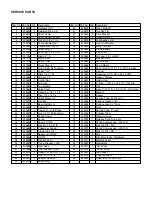
Page 8: ...SERVICE PARTS Figure 8 Replacement parts for HW93720 ...

Page 9: ...over 66 239694 1 Seal 11 16 O D x 7 16 I D 3 16 Deep 22 239650 1 Capscrew 1 4 x 1 3 4 67 239695 1 Magnet 23 239651 1 Pipe 1 4 x 14 3 4 68 239696 1 Spacer 24 239652 2 Street Elbow 1 4 69 239697 1 Suction Tube 22 5 8 Long 25 239653 2 Rod End 70 239698 1 Packing Gasket Felt 26 241081 1 Base Weldment 71 239699 1 Packing Gland 2 Bore 27 239655 2 Caster 4 72 239700 1 Ram 28 239656 2 Caster 4 with Brake ...

Reviews: