


80
2 Installation and Specifications
2.2 Har
dw
a
re
Installation
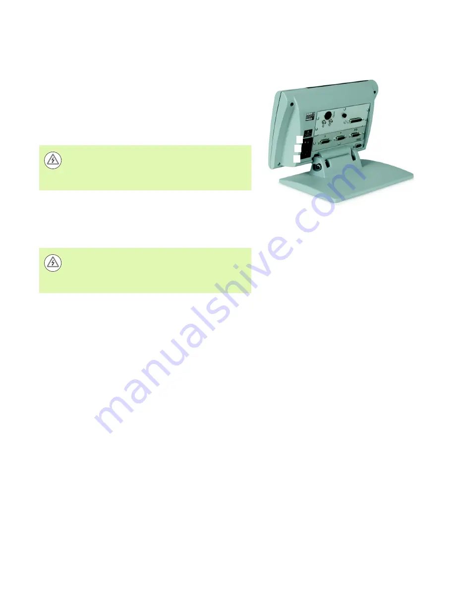
Connecting power
Connect the ND 1200 to power through a high-quality power surge
suppressor. Surge suppressors limit the amplitude of potentially
damaging power line transients caused by electrical machinery or
lightning, and protect the ND 1200 from most power line transients
that can corrupt system memory or damage circuits.
Do not locate the power cord where it can be walked on or will create
a tripping hazard. Connect the 3-wire power plug to only a 3-wire
grounded power outlet.
The power connector assembly includes:
Power switch, fuse and connector
1
2
1
3
Never connect 2-wire to 3-wire adapters to the power cord
or remove the third ground wire to fit the plug into a 2-wire
electrical outlet. Modifying or overriding the third-wire
ground creates a safety hazard and should not be
permitted.
1
Power switch
2
Fuse compartment
3
Power cord connector
Always disconnect the power cord from the source of AC
power before unplugging it from the ND 1200 power
connector. The AC voltage available at electrical outlets is
extremely dangerous and can cause serious injury or
death.
Summary of Contents for ND 1200 - V2.16
Page 1: ...Operating Instructions ND 1200 QUADRA CHEK Software Version 2 16 English en 4 2009...
Page 2: ......
Page 8: ...8 Preface...
Page 13: ...Operation...
Page 74: ...74 1 Operation 1 10 Error Indications...