


2
Software Setup
Certain essential operating parameters
of the IK 5000 must be configured prior
to using the system for the first time.
Many additional factory default
parameters can be changed later to
accommodate specific application
requirements, however, the essential
settings discussed in subsequent pages,
combined with the factory defaults
will be adequate to begin operating
standard IK 5000 systems. Please refer
to the
IK 5000 OEM Setup Guide
at
www.heidenhain.de
for details
regarding all setup parameters for the
standard IK 5000 product family.
Additional software drivers will need to
be installed for systems that utilize USB
cameras for video edge detection.
Follow the installation and setup
instructions in the order presented,
and skip steps that do not apply to
your system. Instructions will be found
under headings that indicate the target
systems:
•
All Systems
indicates instructions for
all IK 5000 systems
•
CNC Included
indicates instructions
for systems that include CNC control
•
Optical Edge Included
indicates
instructions for systems that include
optical edge detection
•
Video Edge Included
indicates
instructions for systems that include
video edge detection
•
Touch Probe Included
indicates
instructions for systems that include a
touch probe
All Systems
1. Turn the PC power on
Launch the PC operating system.
2. Install the video camera driver
If your system utilizes a digital video
camera, follow the manufacturer’s
instructions to install and test the video
camera. Restart your system after the
installation.
3. Install the IK 5000 software
Insert the IK 5000 CD into the CD ROM
drive and follow the instructions shown
on the screen to install the IK 5000
software. The PC will restart after the
installation.
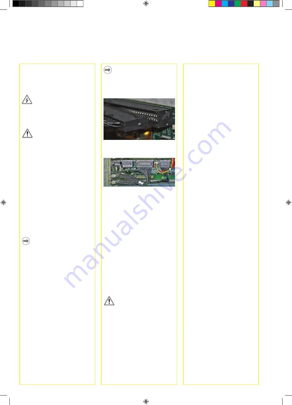
Note
Plug the cables into IK 5000 connectors
C, D and F at the top of the card with
the cable connector flanges facing
down.
Flyout cable connection to IK 5000
PC card
Flyouts connected to IK 5000 PC
card connectors C, D and F
7. Close the PC enclosure
Confirm that all cards, cable connections
and flyouts are securely fastened and
then replace the PC covers or panels.
8. Connect all other system hardware
Refer to the
Card, Flyout and
Connector Configuration
diagram
for your specific system shown earlier
and connect all other system hardware
to the IK 5000 card, flyouts and PC
motherboard connectors.
9. Connect the PC power cable
Confirm that the PC power switch is in
the OFF position and then connect the
PC power cable to the PC and then to
the power source.
Caution
Attach to the power source through a
high-quality electrical surge suppressor
to prevent damage to the PC and
IK 5000 card due to power line
transients.
PC Card and Flyout installation
The installation of the IK 5000 PC card
and associated flyouts requires only
a screwdriver and personal antistatic
protection.
Danger of electrical shock!
Never work in an open enclosure
when power is connected. Disconnect
the power cable before opening the
enclosure.
Caution
Attach antistatic protection such as a
foot strap or wristband before installing
IK 5000 hardware into your PC to
prevent damage to circuit devices.
1. Disconnect power from the PC
2. Open the PC enclosure
Remove any covers or panels to
gain access to the motherboard PCI
expansion slots.
3. Remove flyout blanks
Refer to the
Suggested PC Card and
Flyout Placement
diagram near the end
of this guide and remove flyout blanks
to accommodate the IK 5000 card and
flyouts provided for your system.
Note
The card and flyout locations apply to
most PCs with multiple expansion slots.
Your PC might require different card or
flyout positioning.
4. Install the IK 5000 card
Carefully plug the IK 5000 card into a
PCI slot location. Limit card handling to
the card edges as much as possible and
secure the card with a bracket screw.
5. Install flyouts
Install the flyouts for your system into
the appropriate locations and secure
with bracket screws.
6. Connect flyout cables to the card
Plug the internal flyout cables and power
cable for your IK 5000 application into
the appropriate card connectors. Refer
to the
Card, Flyout and Connector
Configuration
diagrams on earlier
pages for the correct cable connections.
Installation and Setup


