


Installation | Connecting touch probes
5
5.5
Connecting touch probes
The following touch probes can be connected to the unit:
HEIDENHAIN TS 248 touch probe
HEIDENHAIN KT 130 edge finder
Renishaw touch trigger probe
"Items supplied and accessories", Page 30
Comply with the pin layout
Remove and save the dust protection cap
Route the cables depending on the mounting variant
"Assembly of the product", Page 36
Connect the touch probe firmly
If the cable connectors include mounting screws, do not overtighten them
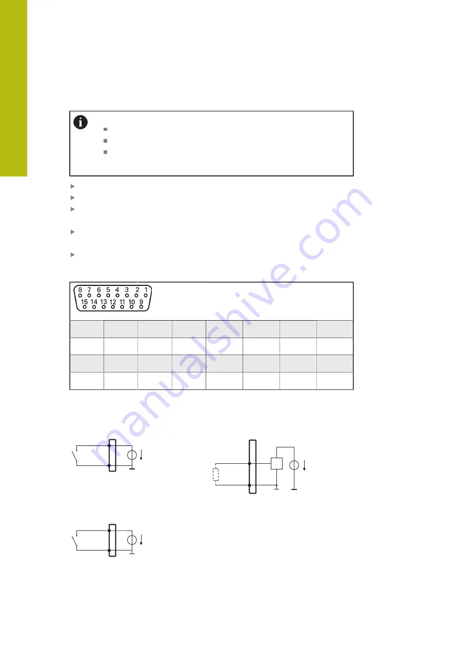
Pin layout of X113
1
2
3
4
5
6
7
8
LED+
B 5 V
B 12 V
Dout 0
DC 12 V
DC 5 V
Din 0
GND
9
10
11
12
13
14
15
Din 1
Din 2
TP
GND
TP
Din 3
LED–
B – Probe signals, readiness
TP – Touch Probe, normally closed
Digital inputs:
Digital outputs:
Din 0...3
X113
GND
DC 5 V
Dout 0
GND
X113
DC 5 V
TTL
Touch probe:
TP
X113
GND
DC 5 V
46
HEIDENHAIN | GAGE-CHEK 2000 | Operating Instructions | 08/2020
Summary of Contents for GAGE-CHEK 2000 Series
Page 1: ...GAGE CHEK 2000 Operating Instructions Evaluation Unit English en 08 2020 ...
Page 12: ......
Page 13: ...1 Fundamentals ...
Page 22: ......
Page 23: ...2 Safety ...
Page 28: ......
Page 29: ...3 Transport and storage ...
Page 34: ......
Page 35: ...4 Mounting ...
Page 41: ...5 Installation ...
Page 51: ...6 Basic operation ...
Page 74: ......
Page 75: ...7 Commissioning ...
Page 119: ...8 Setup ...
Page 154: ......
Page 155: ...9 Measuring ...
Page 169: ...10 File management ...
Page 176: ......
Page 177: ...11 Settings ...
Page 210: ......
Page 211: ...12 Servicing and maintenance ...
Page 220: ......
Page 221: ...13 What to do if ...
Page 225: ...14 Removal and disposal ...
Page 227: ...15 Specifications ...