background image

Clearance distances

It is recommended that a minimum
clearance of 100mm is allowed
around the case and 55mm above.
The clearance allows for cable entry
and prevents combustible surfaces
overheating.

The minimum mounting height (floor
to grille) is 2m. The recommended
mounting height is 3m.

Health and Safety

Sole liability rests with the installer to
ensure that all site safety procedures
are adhered to including the use of
protective safety wear such as hand,
eye, ear and head protection.

Do not rest anything especially ladders
against the product.

Installation

It is the sole responsibility of the installer to ensure that the points of
attachment to the building are sound. Consultation with the consultant/
architect or owner of the building is recommended to ensure that a sound,
mechanically stable installation is achieved.

Before fitting or wiring the air curtain, ensure the casing faces the direction
shown in figure 3.

Using a pozidrive screwdriver slacken the two M5 screws in the corners
near air inlet side and remove the two M5 screws in opposite corner near
the outlet.

Slide the lid sideways until the keyhole slots pass over the screw heads. The
grille assembly can now be removed from the case.

Each unit has 2 fixing brackets from which it is suspended.

The brackets may be removed to assist in passing the air curtain through
the recess then reattached when in-situ.

Either drop rods or catenary wire can be used to fasten the air curtain to
the ceiling support structure.

4

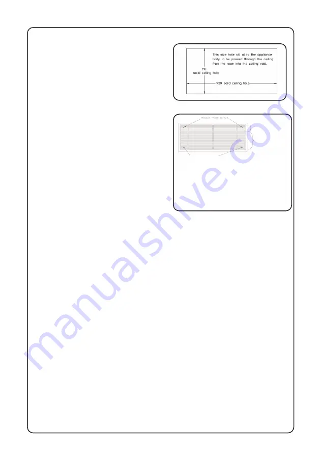
Figure 6:  Ceiling grille fixing detail.

Slacken these screws.

Slide grille sideways until keyhole slots pass
over screw heads and lid can be removed
from unit. An earth lead is connected to the
lid from the unit body, push on connection
at grille. When replacing the grille onto the
unit, ensure Earth lead is re-connected.

Figure 5:  Ceiling cut-out 6kW model.

Air outlet section of lid

Air inlet section of lid

Summary of Contents for HSACR X Series

Page 1: ...AYS BE FOLLOWED PLEASE READ ALL INSTRUCTIONS CAREFULLY AND RETAIN FOR FUTURE REFERENCE IF IN ANY DOUBT ABOUT THE INSTALLATION OR USE OF THIS PRODUCT CONSULT A COMPETENT ELECTRICIAN HSACR X Recessed Ceiling Heaters Installation and Operating Instructions for use with the standard remote switch ...

Page 2: ... General Information All installations must be in accordance with the regulations in force in the country of use Installers and service engineers must be able to demonstrate competence and be suitably qualified To ensure continued and safe operation it is recommended that the appliance is serviced annually The heater outlet inlet must not be obstructed during use Dimensions This manual describes i...

Page 3: ...switch is connected in the mains supply Before Installation Mounting location It is recommended that the air curtain is installed on the inside of the building The units should be installed horizontally directly over the door opening or within the ceiling void or roof space Care must be taken to allow complete free air movement into the inlet grilles of the unit to ensure correct working operation...

Page 4: ... wiring the air curtain ensure the casing faces the direction shown in figure 3 Using a pozidrive screwdriver slacken the two M5 screws in the corners near air inlet side and remove the two M5 screws in opposite corner near the outlet Slide the lid sideways until the keyhole slots pass over the screw heads The grille assembly can now be removed from the case Each unit has 2 fixing brackets from wh...

Page 5: ...10 Mains supply via remote switch 5 The height between the ceiling face and the top of the air curtain case needs to be adjusted to circa 140mm to enable the grille assembly to fit flush with the ceiling Adjust accordingly After fitting the product in the ceiling recess and adjusting the height to ensure that the grille sits flush to the ceiling when re fitted take the grille assembly and refit us...

Page 6: ...ply it will be necessary to open the terminal cover at the side back of the unit to connect the supply from the controls prior to refitting the cover Wire in accordance to the wiring diagrams For safety reasons a sound earth connection must always be made to the unit before it is put to use The unit should be wired in accordance with IEE Figure 12 Circuit Diagram 3kW model Figure 11 Wiring of heat...

Page 7: ...functions ON OFF and HEAT For thermostatic control a room thermostat of appropriate switch rating maybe connected to the circuit The thermostat should be wired between the isolator switch and the heater remote switch To control more than one heater by a thermostat a contactor or a relay in conjunction with the thermostat should be used To switch on the appliance and operate the fan depress the lef...

Page 8: ...fied using conventional fault finding techniques Thermal cut out These units are protected from overheating by thermal cut outs in the event of fan failure or an obstruction of the free airflow If this happens the thermal cut outs switch off the appliance The appliance will not operate until the heater is disconnected from the mains supply and it has cooled down If this fault re occurs again conta...

Reviews: