Heateflex SX-36-3V-P510 Instruction Manual Download Page 11


11 

405 E. Santa Clara St., Arcadia, CA 91006-7218 

O

: (626) 599-8566 


F

: (626) 599-9567 


I

NSTALLATION 

P

ROCEDURES


Installation of this unit consists of first verifying that the minimum facility requirements for normal 
operation can be met.  Once the mounting requirements are completely understood and it has 
been verified that they can be met, the next step would be locating where the unit will be used. 

The unit should then be fastened in a manner consistent with the accompanying documentation 
with the appropriate mounting hardware and then a final check should be made to ensure that all 
venting  and  clearance  requirements  are  met  before  connecting  incoming  power.    It  is  also 
recommended that the minimum safety requirements be met, prior to initial unit power-on.  The 
unit must be mounted in such a position that it does not exceed a tilt of 10° in either the vertical 
or horizontal directions.   

Once the unit is secured in its operational position, the water lines can be introduced.  The input 
can be brought directly to the appropriately labeled connector on the left side of the cabinet. For 
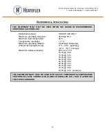
the  types  of  fittings  included,  refer  to  the  Equipment  Specifications  on  page  5.    Once  the 
appropriate plumbing has been connected, water should be run through the system without the 
power connected to check for leaks.  If no leaks are present, incoming power and the appropriate 
signals may be brought in. 

Incoming power  should be brought in through the conduit fitting located on the top right of the 
cabinet.  Also, an appropriately sized external disconnect switch should be used with the unit to 
protect  the  operator  during  servicing.  Incoming  power  can  be  brought  into  the  unit,  after  the 
appropriate  external  fused  disconnect  switch,  or  circuit  breaker.  For  the  incoming  power 
requirements, refer to the Equipment Specifications on page 5.  Please insure that the external 
disconnect is in the off position while you are attaching the incoming power, and refer and review 
the  “Basic  Safety  Precautions”  section  of  this  manual  on  pages  7-8  before  attempting  any 
electrical work.  Once the incoming power connections are secure, be sure that the cabinet door 
is closed and locked before activating the external disconnect.  Once these conditions are met, 
refer to the section of this manual titled “Basic Operation,” on pages 10-11. 
 

Summary of Contents for SX-36-3V-P510

Page 1: ...rld Leader in Ultra Pure Heating www heateflex com 405 E Santa Clara St Arcadia CA 91006 7218 O 626 599 8566 F 626 599 9567 HEATEFLEX CORPORATION SX 36 3V P510 STAINLESS STEEL HEATER INSTRUCTION MANUA...

Page 2: ...405 E Santa Clara St Arcadia CA 91006 7218 O 626 599 8566 F 626 599 9567...

Page 3: ...ntroduction Description Equipment Specifications Environmental Specifications Basic Safety Precautions Installation Procedures Operating Instructions Quality Control Sheet Suggested Spare Parts List W...

Page 4: ...NG INSTRUCTIONS 5 RECEIVING INSPECTION PROCEDURE 5 INTRODUCTION 6 DESCRIPTION 6 EQUIPMENT SPECIFICATIONS 7 ENVIRONMENTAL SPECIFICATIONS 8 BASIC SAFETY PRECAUTIONS 9 INSTALLATION PROCEDURES 11 OPERATIN...

Page 5: ...FACTORY THEREFORE WHEN IT IS DELIVERED TO THE CARRIER IT BECOMES YOUR PROPERTY THUS IT IS IMPORTANT THAT YOU TAKE NOTE OF ANY DAMAGE WHETHER OBVIOUS OR HIDDEN REPORT THIS INFORMATION TO THE TRANSPORT...

Page 6: ...ultra high purity environment It is a high tech piece of equipment incorporating many design innovations and precautionary measures to insure safe and reliable operation under normal conditions This...

Page 7: ...oltage 480 VAC Hertz 60 Hz Number of phases 3 phase Current per phase 43 Amps Phase Inlet Connector 2 1 2 Sanitary Ferrule Outlet Connector 2 1 2 Sanitary Ferrule Drain Port 1 2 Sanitary Ferrule Press...

Page 8: ...Maximum fluid temperature 95 C Temperature resolution 1 C Maximum operating altitude 6 600feet 2 000meters Ambient temperature range 5 C 40 C operating 40 C 60 C storage Maximum relative humidity 80 u...

Page 9: ...mponents can develop temperatures that produce an auto ignition source Avoid mounting heaters in atmospheres containing combustible gases vapor or dust Article 501 of the National Electrical Code NEC...

Page 10: ...ibility to verify that incoming power has been disconnected from a remote source prior to opening or servicing the unit This is advised to prevent user exposure to high voltage and current and reduce...

Page 11: ...the left side of the cabinet For the types of fittings included refer to the Equipment Specifications on page 5 Once the appropriate plumbing has been connected water should be run through the system...

Page 12: ...set point to the required temperature This is accomplished by the following Refer to the temperature controls panel Verify that it is displaying the process temperature in the proper units If it is n...

Page 13: ...ic Due to the manner in which this unit operates it does not require regular re calibration or maintenance The only sort of calibration that is required is the Auto Tuning process This process is used...

Page 14: ...33 ALS 0 0 34 F41 ES1 5 35 F41 EHo1 0 36 F41 E1L1 0 37 F41 EH1 2 0 38 F41 EVT1 0 0 39 F41 Eeo1 0 40 F42 ES2 0 41 F42 Eho2 0 42 F42 E1L2 0 43 F42 EH2 2 44 F42 EVT2 0 0 45 F42 EEo2 0 Function Symbol Set...

Page 15: ...F52 dcAJ 1 00 118 F53 Ydb 2 0 119 F53 YHS 1 120 F53 Ybr 0 121 F53 PoS AdJ 122 F53 moT 10 123 F53 oLA 150 0 124 F53 VAL 0 125 F54 STS 0 126 F54 STPK 1 00 127 F54 ST1K 1 00 128 F54 STdK 1 00 129 F55 CH...

Page 16: ...er 2A 480VAC 2 Poles 11 1 309810 Transformer 380 480VAC 120V 24V 12V 12 1 300377 Contactor 3P 24VAC 50 60Hz 13 4 300108 Relay DPDT 24VAC DC Coil 14 4 300107 Relay SPDT 24VAC DC Coil 15 1 301010 Fuse G...

Page 17: ...in workmanship or material which may develop under normal handling and proper usage during a period of one year from the date of shipment or by its option to repair or replace the defective equipment...

Reviews: