Heat-N-Glo 6000TRS-AUB Assembly, Installation And Operation Instructions Download Page 21

21

1.8  INSTALLER TESTING

The space heater must be tested and be operating ac-
cording to manufacturers specifications prior to the in-
staller leaving the site. Note: the tips of the flames
should never hit the top of the firebox after the unit has
warmed up. Please contact your dealer or a qualified
service person to replace injector or adjust valve.

Upon completing the gas line connection, a small
amount of air will be in the lines. When first lighting the
pilot light, it will take a few minutes for the lines to
purge themselves of this air.  Once the purging is com-
plete, the pilot and burner will light and operate as indi-
cated in the Lighting Instructions.

Subsequent lightings of the appliance will not require
such purging.

CAUTION: DURING THE INITIAL PURGING AND
SUBSEQUENT LIGHTINGS, NEVER ALLOW THE
GAS VALVE CONTROL KNOB TO REMAIN DE-
PRESSED IN THE "PILOT" POSITION WITHOUT
PUSHING THE RED IGNITOR BUTTON  AT LEAST
ONCE EVERY SECOND.

Follow the Safety Information and Lighting Instructions
pages of this manual to light the appliance.

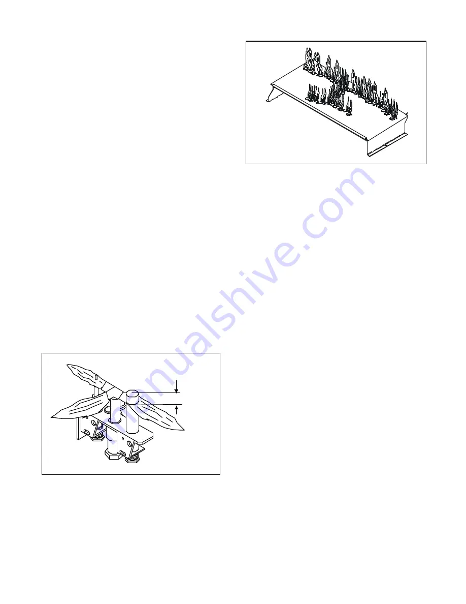
To obtain proper operation, it is imperative that the pi-
lot and main burner flame characteristics are steady,
not lifting or floating.  Typically, the top 3/8-inch (9.5mm)
at the pilot generator should be engulfed in the pilot
flame. (Figure 29)

FIGURE 29.

FIGURE 30.

Standing Pilot

3/8" (9.5mm)

2.0  OPERATING INSTRUCTIONS

This appliance is a balanced flue heater and is designed
to operate with all combustion air being siphoned from
the outside of the building and all exhaust gases ex-
pelled to the outside of the building.

WARNING: THIS UNIT IS NOT FOR USE WITH SOLID
FUEL.

The control system for this model is a millivolt type. It
consists of a gas control valve/variable regulator, a stand-
ing pilot assembly, a thermopile/thermocouple assem-
bly, a piezo ignitor, an ON/OFF rocker switch and a safety
high temperature limit switch. The controls  are located
in the lower compartment behind the lower door, and ac-
cess is gained by lifting the door up. See Figure 1.

WARNING: DO NOT CONNECT 220-240 VAC TO THE
GAS CONTROL VALVE OR CONTROL WIRING SYS-
TEM OF THIS UNIT.

The gas control system is wired so the thermopile, when
heated with the pilot light, will provide approximately 350
to 500 millivolts. This activates the gas control valve. See
Figure 31 for appliance wiring diagram.

Additionally, a high temperature limit switch is wired to
ground and will shut-off the pilot and burner should a
high surface temperature condition occur. The pilot and
main burner must be re-lit when the heater cools. See
Figure 31.

When lit for the first time, the appliance will emit a slight
odor for an hour or two. This is due to paint and lubri-
cants used in the manufacturing process. Additionally,
for the first few minutes after each lighting, vapor may
condense and fog the glass and the flames may be blue.
After a few minutes this moisture will disappear and within
15-30 minutes the flames should become yellow.

The heater may produce a noise, caused from metal
expansion and contraction as it heats up and cools down.
This noise is similar to one that a furnace or heat duct
may produce and does not affect the operation or lon-
gevity of the heater.

Burner flame patterns are shown in Figure 29.

Follow Section 3.5 TROUBLESHOOTING for adjusting
the appliance to operate properly.

Summary of Contents for 6000TRS-AUB

Page 1: ...044 USA 1 888 427 3973 2022 900F 7 04 INSTALLATION AND OPERATION INSTRUCTIONS This product is covered by one or more of the following patents United States 4 112 913 4 408 594 4 422 426 4 424 792 4 52...

Page 2: ...ual Report to your dealer any parts dam aged in shipment specifically check glass condi tion The gas logs and flue system components are in separate packages Read all instructions before INSTALLATION...

Page 3: ...staller Testing 21 2 0 OPERATING INSTRUCTIONS 21 2 1 Safety and Lighting Information 23 2 2 Safety Information 23 2 3 Lighting Instructions 24 2 4 Fan Operation 25 3 0 SERVICING AND MAINTENANCE 25 3 1...

Page 4: ...r remote control are desired If the heater is to be installed on carpeting or tile or on any combustible material other than wood flooring the heater should be installed on a metal or wood panel that...

Page 5: ...Locating the Heater The diagram See figure 2 shows space and clearance requirements for locating a heater within a room Minimum Clearances from the Heater to Combustible Materials Glass Back of Sides...

Page 6: ...ERIFY FRAMING METHODS AND WALL COVER ING DETAILS BEFORE FRAMING CONSTRUCTION BEGINS NOTE Dimension B taken from finished hearth frame Dimensions D and E taken from bottom of unit For minimum clearance...

Page 7: ...input 300 Appliances over 50 MJ h input 500 b From the ground or above a balcony 300 c From a return wall or external corner 500 d From a gas meter M 1000 e From an electricity meter or fuse box P 50...

Page 8: ...are listed as TOTAL MAXIMUM verti cal dimensions FIGURE 5 V CAP V MAX RUN 36 FT 10 9m FIGURE 4 1 3 FLUE SYSTEM APPROVALS AND INSTALLA TIONS This model is approved to use DVP Series flue pipe component...

Page 9: ...M V FT H FT 1 MIN 305mm 4 MAX 1 22m 2 MIN 610mm 8 MAX 2 4m 3 MIN 914mm 12 MAX 3 7m 4 MIN 1 22m 16 MAX 4 9m V H 24 MAX 7 3m H 8 MAX 2 4m FIGURE 8 Flueing with One 90 Elbow NOTE If a 90o elbow is first...

Page 10: ...3 MIN 914mm 4 MAX 1 22m 12 MAX 3 72m 4 MIN 1 22m 6 MAX 1 8m 16 MAX 4 9m 20 MAX 6 1m 6 MAX 1 8m 16 MAX 4 9m FIGURE 10 Flueing with Two 90 Elbows V FT H H1 FT 1 MIN 305mm 4 MAX 1 22m 2 MIN 610mm 8 MAX 2...

Page 11: ...3 6 m 4 MIN 1 22 m 8 MAX 2 48 m 16 MAX 4 9 m 8 MAX 2 48 m 16 MAX 4 9 m NOTE V V MAX 36 10 9 m FLUEING WITH THREE 3 90 ELBOWS FIGURE 11 Flueing with three 90 elbows V H H H1 H2 1 MIN 305 mm 2 MAX 610...

Page 12: ...914mm 12 MAX 3 7m 4 MIN 1 22m 16 MAX 4 9m NOTE H H1 16 MAX 4 9m V V1 H H1 36 MAX 10 9m V FT H H1 FT 1 MIN 305mm 4 MAX 1 22m 2 MIN 610mm 8 MAX 2 4m 3 MIN 914mm 12 MAX 3 7m 4 MIN 1 22m 16 MAX 4 9m H H1...

Page 13: ...ling Flue Components After determining which set of starting collars will be used top or rear follow flueing instructions accordingly Flueing Out the Rear Flue Remove the installed rear seal cap from...

Page 14: ...pre viously cut and secure the firestops with nails or screws The pipe opening of the firestops MUST BE placed towards the bottom of the firestop Continue the flue run through the firestop FIGURE 18...

Page 15: ...me manner The heat shield sections will overlap to match the wall thickness depth The small leg in the shield rests on top of the flue to properly space it from the pipe section see Figure 22 JOIST CE...

Page 16: ...ical flue pipe to combus tible materials Mark the roof hole accordingly Cover the opening of the installed flue pipes Cut and frame the roof hole Use framing lumber the same size as the roof rafters a...

Page 17: ...E BRN BR N BLUE GRD BLUE JUNCTION BOX DETAIL FAN TEMPERATURE SENSOR SWITCH FAN SPEED CONTROL JUNCTION BOX 1 5 FAN These heaters have a factory installed Fan Electrical Junction Boxes variable speed Rh...

Page 18: ...SEALED A 150 C MINIMUM SEALANT MATERIAL MUST BE USED THESE JOINTS ARE NOT REQUIRED TO BE SEALED ONLY NON COMBUSTIBLE MATERIAL USING 150 C MINIMUM ADHESIVE IF NEEDED CAN BE APPLIED A S FACING TO THE F...

Page 19: ...cate log 1 on grate with notches and push log against rear log locators LOG 2 SRV382 702 Locate log 2 on grate with notches Slide left end of log forward and right side back against tab Log Assembly L...

Page 20: ...the right end on top of log 2 LOG 5 SRV382 705 Place bottom of log 5 between the 4th and 5th grate bars and rest the top onto log 1 LOG 6 SRV438 724 Place the Y shaped part of log 6 over the 3rd grate...

Page 21: ...he building WARNING THIS UNIT IS NOT FOR USE WITH SOLID FUEL The control system for this model is a millivolt type It consists of a gas control valve variable regulator a stand ing pilot assembly a th...

Page 22: ...E THE UNIT CAN BE PLACED INTO SAFE OP ERATION DO NOT USE THIS APPLIANCE IF ANY PART HAS BEEN UNDER WATER IMMEDIATELY CALL A QUALIFIED SERVICE TECHNICIAN TO INSPECT THE UNIT AND TO REPLACE ANY PART OF...

Page 23: ...has been under water Immediately call a qualified service technician to inspect the appliance and to replace any part of the gas control system which has been under water 2 1 SAFETY LIGHTING INFORMATI...

Page 24: ...houldnotrequireaccessingforlighting purposes The pilot is located inside the combustion chamber THERMOPILE PILOT BURNER 6 To put the control in the pilot position turn the control knob counter clockwi...

Page 25: ...sh ing at least twice a year CAUTION THE LOGS GET VERY HOT HANDLE ONLY WHEN COOL WARNING DO NOT USE ABRASIVE CLEANERS ON THE GLASS DOOR ASSEMBLY DO NOT ATTEMPT TO CLEAN THE GLASS DOOR WHEN IT IS HOT F...

Page 26: ...m the underside of the thermopile The thermopile can then be sepa rated from the pilot bracket Unscrew the pilot assembly bracket and remove NOTE When removing the pilot assembly carefully pull the el...

Page 27: ...gnitor 1 Using a match light pilot If pi lot lights turn off pilot and trig ger the red or black button again If pilot lights an improper gas air mixture caused the bad light ing and a longer purge pe...

Page 28: ...micro switch and connect to terminal TP on the gas valve Turn green knob to pilot position depress and light pilot light If meter reading is greater than 325 m v after 30 seconds the pilot generator i...

Page 29: ...allow for igni tion or the heater continues to shut off disconnect the limit switch wire from the gas valve and repeat the lighting instruc tions If the pilot and burner re main lit after the heater...

Page 30: ...debris or blockage 1 Adjust the log set so that the flame does not impinge on it 1 Adjust the air shutter at the base of the burner 1 Inspect the opening at the base of the burner It is imperative th...

Page 31: ...31 6000TRS AUB Exploded Parts Diagram 4 0 Replacement Parts Service Parts List on following page 21 Log set assembly 27 24 26 25 22 23 5 16 17 2 1 19 20 3 15 14 13 12 18 4 7 6 8 11 9 10 29 28 30 31...

Page 32: ...9 13 Blower Assembly 240v 100 505A 14 Junction Box 546 250A 15 Cord 546 251A 16 Pilot Assembly NG 530 510A Pilot Assembly LP 530 511A 17 ON OFF Rocker Switch 060 511 18 Heat Shield Baffle 2022 100 19...

Page 33: ...t the current wholesale price defective electrical or manual components optional components or accessories and glass panels not including glass panels broken during misuse or careless handling HEAT N...

Reviews: