


15
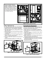
Figure 12. Alternate Removal Method
1
4
2
7
3
6
5
Alternate Bottom Panel Removal
If the bottom panel cannot be removed using the previous
instructions, the steps below are an alternate method for
removing the bottom panel. See Figure 12.
1. Remove the door (1) from the blower compartment .
2. Remove all screws securing the bottom panel (2) to the
front brace (3).
3. Remove two screws (4) securing the furnace cabinet
to the blower deck (5).
4. Remove all screws (6) securing the furnace cabinet to
the bottom panel (2).
5. Remove the screw (7) securing the bottom corner of
the furnace cabinet to the front brace (3).
6. Carefully spread the bottom corner of the furnace cabinet
outwards while sliding the bottom panel (2) out through
the front of the furnace.
7. Reassemble the furnace in reverse order.
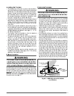
Bottom Panel Removal
The steps listed below explain the proper method for
removing the bottom panel from the furnace. See Figure 11.
1. Remove the door (1) from the blower compartment.
2. Disconnect the blower motor wiring harness (2) from
the control board.
3. Remove two screws (3) securing the blower assembly
(4) to the furnace.
4. Carefully pull the blower assembly (4) out thru the front
of the furnace.
5. Remove all screws (5) securing bottom panel (6) to
bottom of furnace and front brace (7).
6. Lift up and slide bottom panel (6) out through front of
furnace.
7. Reinstall the blower assembly (4) in reverse order.
6
7
5
1
2
3
4
Figure 11. Bottom Panel Removal
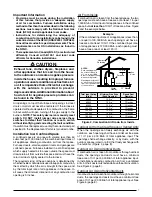
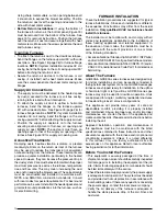
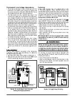
Pressure Switch Tubing
Figure 10 displays the proper
routing of pressure switch tubing for
GUH80A & GDD80A furnaces. On
both furnaces, the tubing connects at
one end of the pressure switch and
is routed directly onto the static tap
of the inducer assembly.
Figure 10. Pressure Switch Tubing


