background image

Heat & Glo  •  RED60  •  2159-900 Rev. B  •  12/09

72

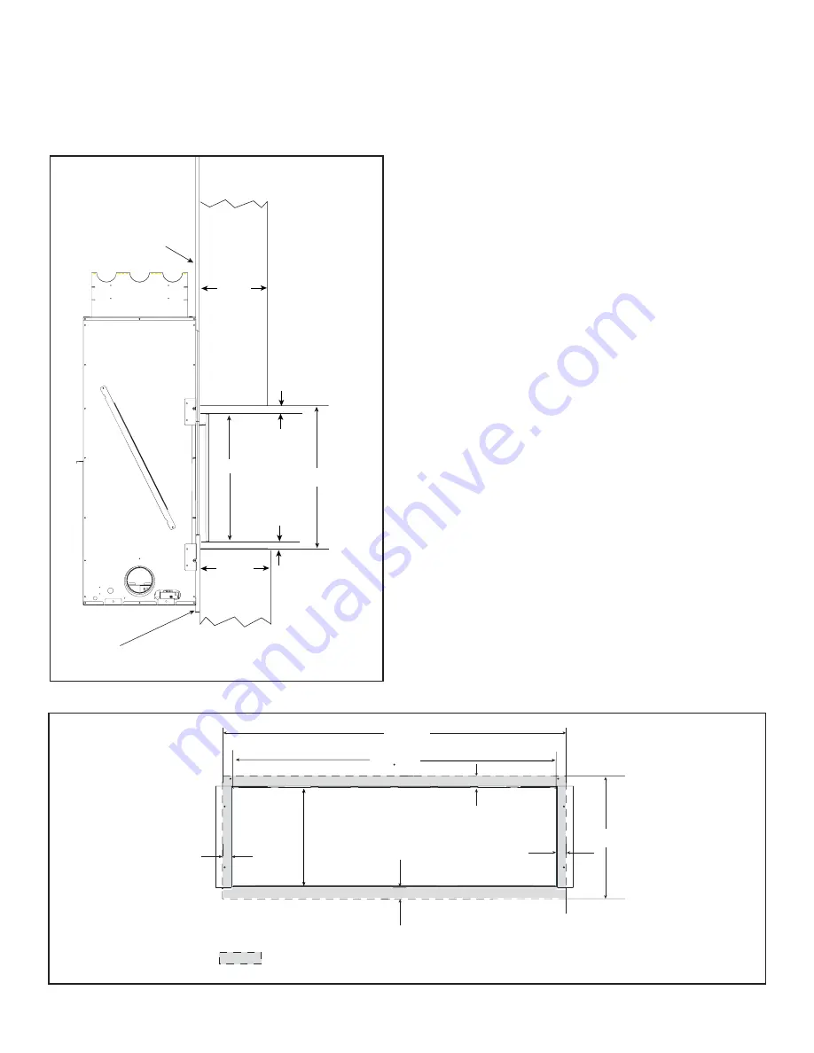
Figure 13.11  Noncombustible Surface Finishing Material 0-4 Inches Thick-Inside Fit Method

The mesh decorative front is approved for inside fi t  ap-
plications. Non-combustible fi nishing materials up to 4 
inches thick can be installed around the Mesh front (left, 
right, top, and bottom).  See Figure 13.10.

Figure 13.10  Inside Fit Method

Non-Combustible Finish Materials
0 Inches to 4 Inches Thick-Inside Fit Method

1/2 IN. THICK

WALL SHEATHING

0-4 IN.

20-1/2 IN. 

0- 4 IN.

1/2 IN.

1/2 IN.

19-1/2 IN. 

DRYWALL OR 
EQUIVALENT (1/2 IN.)

1-11/16 IN.

1-11/16 IN.

20-1/2 IN.

1-3/8 IN.

1-3/8 IN.

65-1/2 IN.

FIREPLACE VIEWING AREA

= CLEARANCE FROM VIEWING AREA TO NON-COMBUSTIBLE FINISHING MATERIAL
   (INSIDE FIT METHOD)

17-1/8 IN.

62-3/4 IN.

Ensure that no non-combustible fi nish materials are in-
stalled within 1-11/16 inches of top and bottom and 1-3/8 
inches from right and left sides of fi replace opening.  This 
will ensure adequate clearance for required mesh front.  
See Figure 13.11.

Refer to Section 1.E and 1.F of this manual for defi nition 
and qualifi cations and defi nition of non-combustible and 
combustible materials.

Summary of Contents for RED60

Page 1: ...rating plate Installation and service of this appliance should be performed by qualified personnel Hearth Home Technologies suggests NFI certified or factory trained professionals or technicians supervised by an NFI certified professional Leave this manual with party responsible for use and operation DO NOT DISCARD WARNING Important operating and maintenance instructions included Read understand a...

Page 2: ...ler l appareil l appareil selon selon les les codes codes ou ou reglements reglements locaux locaux ou ou en en l absence l absence de de tels tels reglements reglements selon selon les les codes codes d installation d installation CAN CGA B149 CAN CGA B149 Type Type of of Gas Gas Sorte Sorte De De Gaz Gaz N NA ATURAL TURAL GAS GAS MADE MADE IN IN USA USA Minimum Minimum Permissible Permissible Ga...

Page 3: ...ce and Components 16 5 Framing and Clearances A Selecting Appliance Location 17 B Constructing the Appliance Chase 18 C Clearances 18 D Mantel and Wall Projections 20 6 Termination Locations A Vent Termination Minimum Clearances 21 7 Vent Information and Diagrams A Approved Pipe 23 B Vent Table Key 23 C Use of Elbows 23 D Measuring Standards 23 E Vent Information 23 F Installation Instructions and...

Page 4: ...rial 70 E Mesh Fronts 73 14 Appliance Setup A Remove Fixed Glass Assembly 74 B Remove the Shipping Materials 74 C Clean the Appliance 74 D Accessories 74 E Glass Rock Media Instructions 74 F Porcelain Instructions 74 G Granite Instructions 74 H Fixed Glass Assembly 75 I Install the Mesh 75 J Air Shutter Setting 75 15 Troubleshooting A IntelliFire Ignition System 76 16 Reference Materials A Applian...

Page 5: ...Heat Glo RED60 2159 900 Rev B 12 09 5 B Limited Lifetime Warranty ...

Page 6: ...Heat Glo RED60 2159 900 Rev B 12 09 6 B Limited Lifetime Warranty continued ...

Page 7: ...ations such as in bathrooms or near sinks NOT INTENDED FOR USE AS A PRIMARY HEAT SOURCE This appliance is tested and approved as either supplemen tal room heat or as a decorative appliance It should not be factored as primary heat in residential heating calculations D High Altitude Installations NOTICE If the heating value of the gas has been reduced these rules do not apply Check with your local ...

Page 8: ...ing appliance or equipment The sign shall read in print size no less than one half 1 2 in in size GAS VENT DIRECTLY BELOW KEEP CLEAR OF ALL OB STRUCTIONS Inspection The state or local gas inspector of the side wall horizon tally vented gas fueled equipment shall not approve the installation unless upon inspection the inspector ob serves carbon monoxide detectors and signage installed in accordance...

Page 9: ...ch glass Keep children away CAREFULLY SUPERVISE children in same room as fireplace Alert children and adults to hazards of high temperatures High temperatures may ignite clothing or other flammable materials Keep clothing furniture draperies and other flammable materials away Install a switch lock or a wall remote control with child protection lockout feature Never leave children alone near a hot ...

Page 10: ... help is needed to properly install one For more information refer to the instructions supplied with your decorative door or front F Before Lighting Fireplace Before operating this fireplace for the first time have a qualified service technician Verify all shipping materials have been removed from inside and or underneath the firebox Review proper placement of media refractory kits and or other de...

Page 11: ...U SMELL GAS DO NOT try to light any appliance DO NOT touch any electric switch do not use any phone in your building DO NOT CONNECT LINE VOLT AGE 110 120 VAC OR 220 240 VAC TO THE CONTROL VALVE Improper installation adjustment al teration service or maintenance can cause injury or property damage Re fer to the owner s information manual provided with this appliance This appliance needs fresh air f...

Page 12: ...ishing materials and adhesives used near the fireplace These circumstances may require additional curing related to the installation environment Film on the glass This is a normal result of the curing process of the paint Glass should be cleaned within 3 to 4 hours of initial burning A non abrasive cleaner such as gas appliance glass cleaner may be nec essary See your dealer Metallic noise Noise i...

Page 13: ...nt 3 3 Maintenance and Service A Maintenance Tasks Homeowner The following tasks may be performed annually by the homeowner If you are uncomfortable performing any of the listed tasks please call your dealer for a service ap pointment More frequent cleaning may be required due to lint from carpeting or other factors Control compartment burner and circulating air passageway of the fireplace must be...

Page 14: ...ment and Firebox Top Frequency Annually By Qualified Service Technician Tools needed Protective gloves vacuum cleaner dust cloths Vacuum and wipe out dust cobwebs debris or pet hair Use caution when cleaning these areas Screw tips that have penetrated the sheet metal are sharp and should be avoided Remove all foreign objects Verify unobstructed air circulation Burner Ignition and Operation Frequen...

Page 15: ...SULATION SHIELD NOT SHOWN MUST BE USED HERE TO KEEP INSULA TION AWAY FROM VENT PIPE IF ATTIC IS INSULATED SECTION 8 D VENT PIPE PENETRATES ROOF PREFERABLY WITHOUT AFFECTING ROOF RAFTERS SECTION 8 C REQUIRED ACTIVE CONVECTION SECTION 9 C NON COMBUSTIBLE ROOF FLASHING MAINTAINS MINIMUM CLEARANCE AROUND PIPE SECTION 10 VENTING SECTIONS 7 and 8 CEILING FIRESTOP ON FLOOR OF ATTIC SECTION 8 C FRAMING HE...

Page 16: ...eration DO NOT install damaged in complete or substitute components Keep appliance dry C Tools and Supplies Needed Before beginning the installation be sure that the following tools and building supplies are available Tape measure Framing material Pliers High temperature caulking material Hammer Phillips screwdriver magnetic Gloves Framing square Voltmeter Electric drill and bits 1 4 in magnetic P...

Page 17: ...l installation may vary due to individual design preference 1 IN 45 1 IN A E A B C TOP VENT ONE 90 ELBOW ALCOVE INSTALLATION B TOP VENT ONE 90 ELBOW F D B Figure 5 1 Appliance Locations RED60 A B C D E F Inches 75 15 16 70 3 8 107 3 8 See Section D Figure 5 6 5 7 31 7 8 18 3 4 Millimeters 1929 1788 2727 810 476 It is important to follow the framing and finishing instruc tions step by step to ensur...

Page 18: ...ir tightness To further prevent drafts the wall shield and ceiling fire stops should be caulked with high temperature caulk to seal gaps Gas line holes and other openings should be caulked with high temperature caulk or stuffed with un faced insulation If the appliance is being installed on a cement surface a layer of plywood may be placed under neath to prevent conducting cold up into the room C ...

Page 19: ...Rough Opening Vent Pipe Rough Opening Height Rough Opening Depth Rough Opening Width Clearance to Ceiling Combustible Floor Combustible Flooring Behind Appliance Sides of Appliance Front of Appliance Inches 10 51 18 1 4 70 3 8 43 0 0 1 1 36 Millimeters 254 1295 464 1788 1092 0 0 25 25 914 H E MEASURE FROM TOP OF FIREPLACE OPENING I G J F ...

Page 20: ...f The Fireplace UNLIMITED 6 IN MIN 2 IN MIN FIREPLACE OPENING TOP VIEW 4 IN MAX ACCEPTABLE NON COMBUSTIBLE MANTEL LEG ZONE MEASUREMENTS FROM TOP EDGE OF THE OPENING 7 8 9 10 11 12 13 31 TO CEILING 9 10 11 12 8 7 6 25 18 Note For non combustible fireplace finish material marble stone etc specifications refer to Section 13 Note All measurements in inches Non Combustible Mantels MEASUREMENTS FROM TOP...

Page 21: ...0 INCHES MIN H MIN MINIMUM HEIGHT FROM ROOF TO LOWEST DISCHARGE OPENING 6 6 Termination Locations Fire Risk Maintain vent clearance to combustibles as specified DO NOT pack air space with insulation or other materials Failure to keep insulation or other materials away from vent pipe may cause overheating and fire WARNING Gas Wood or Fuel Oil Termination Cap B Gas Termination Cap A If using decorat...

Page 22: ...nsions specified for vinyl or non vinyl siding and soffits 1 There must be 3 feet minimum between termination caps 2 All mechanical air intakes within 10 feet of a termination cap must be a minimum of 3 feet below the termination cap 3 All gravity air intakes within 3 feet of a termination cap must be a minimum of 1 foot below the termination cap See Note 1 See Note 2 Note 3 Local codes or regulat...

Page 23: ...tandards Vertical and horizontal measurements listed in the vent diagrams were made using the following standards Pipe measurements are shown using the effective length of pipe see Figure 7 2 Measurements are made from the appliance outer wrap not from the standoffs Horizontal terminations are measured to the outside mounting surface flange of termination cap Vertical terminations are measured to ...

Page 24: ...king wiring connections g Venting of more than one appliance in a common vent system is prohibited Figure 7 4 Replacement Parts List VACUUM SWITCH 2196 301 BLOWER ASSEMBLY 2196 025 Optional Wire Harness DESCRIPTION PART NUMBER 10 ft PV Wire Harness PVI WH10 20 ft PV Wire Harness PVI WH20 40 ft PV Wire Harness PVI WH40 60 ft PV Wire Harness PVI WH60 80 ft PV Wire Harness PVI WH80 100 ft PV Wire Har...

Page 25: ...VI and the termination cap to allow room for the pipe to go through a wall or roof Framing and Clearances Note The mounting brackets attached to the frame must be used to install the PVI DVP Chassis Dimensions PVI DVP Vertically Positioned as shown in Figure 7 5 and Figure 7 6 Height Width Depth 18 7 8 in 11 5 8 in 13 in Framing Dimensions WARNING Risk of fire and burns DO NOT install PVI with the...

Page 26: ... the access panel This hole may be covered with an open air louvered cover Figure 7 9 Mount PVI SLP to Chase Figure 7 10 PVI SLP Mounted with Fresh Air Access 1 2 IN MAX FROM BACK OF OPEN AIR COVER SHEETROCK ADJUST BRACKET TO SPECIFIED DEPTH LOUVERED OR OPEN AIR WALL COVER Figure 7 10 and Figure 7 11 show the proper installation of the PVI DVP if a louvered register is being used to provide free a...

Page 27: ...13 Figure 7 12 Figure 7 13 Figure 7 14 Figure 7 15 SCREWS SCREWS The optional mounting brackets may come in handy when mounting the PVI to a studded wall See Figure 7 13 Securing the PVI inside a floor joist can be easily done us ing the side brackets See figure 7 14 If the side brackets can t be used or additional support is needed the optional mounting brackets can be used as shown in Figure 7 1...

Page 28: ...es Vacuum Switch Orientation WARNING Risk of Fire and Explosion Install vacuum switch on a vertical plane Failure to follow instructions could result in fire or explosion If the PVI is mounted in a vertical position the vacuum switch needs to be moved To do this loosen and remove the two nuts currently using to secure it to the inside wall of the PVI Move and secure the vacuum switch onto the adja...

Page 29: ...three screws that attach the collar to the wall and the five nuts holding the motor down as shown in Figure 7 20 G Operating Instructions After installation of the power vent follow the operation instructions of the fireplace 1 Turn the fireplace ON OFF switch to ON Note During periods of operation after turning the fire place ON there will be a slight delay before the fireplace ignites This is du...

Page 30: ...fied Failure to keep insulation or other material away from vent pipe may cause fire WARNING Note Use DVP Series components only V1 Minimum V1 H1 Maximum 2 ft 610 mm 60 ft 18 3 m 3 ft 914 mm 70 ft 21 3 m 4 ft 1 2 m 80 ft 24 4 m V1 H1 80 ft 24 4 m Maximum Note Must have 24 inches minimum vertical vent prior to attaching any elbow to the appliance Note PVI DVP can be located in any position except V...

Page 31: ...mponents only V1 Minimum V1 H1 H2 Maximum 2 ft 610 mm 50 ft 15 2 m 3 ft 914 mm 60 ft 18 3 m 4 ft 1 2 m 70 ft 21 3 m V1 H1 H2 70 ft 21 3 m Maximum Note Must have 24 inches minimum vertical vent prior to attaching any elbow to the appliance Note PVI DVP can be located in any position except V1 WARNING Risk of fire and burns DO NOT install PVI DVP with the access panel facing upward Over heating may ...

Page 32: ...in any position except V1 4 Elbows V1 V2 Minimum Total V Total H Maximum 2 ft 610 mm 30 ft 9 1 m 3 ft 914 mm 40 ft 12 2 m 4 ft 1 2 m 60 ft 18 3 m TOTAL V TOTAL H 60 ft 18 3 m Maximum 5 Elbows V1 V2 Minimum Total V Total H Maximum 2 ft 610 mm 30 ft 9 1 m 3 ft 914 mm 40 ft 12 2 m 4 ft 1 2 m 50 ft 15 2 m Total V Total H 50 ft 15 2 m Maximum 6 Elbows V1 V2 Minimum Total V Total H Maximum 2 ft 610 mm 1...

Page 33: ...Heat Glo RED60 2159 900 Rev B 12 09 33 Figure 7 24 Vertical Vent Maximum V1 V2 V1 8 ft Min 2 4 m Top Vent Vertical Termination No Elbows V2 50 ft Max 15 2 m ...

Page 34: ...aximum 2 ft 610 mm 50 ft 15 2 m 3 ft 914 mm 60 ft 18 3 m 4 ft 1219 mm 70 ft 21 3 m V1 V2 H1 70 ft 21 3 m Maximum Note PVI DVP can be located in any position except V1 WARNING Risk of fire and burns DO NOT install PVI DVP with the access panel facing upward Over heating may occur Note Must have 24 inches minimum vertical vent prior to attaching any elbow to the appliance ...

Page 35: ... V1 V2 H1 H2 Maximum 2 ft 610 mm 40 ft 12 2 m 3 ft 914 mm 50 ft 15 2 m 4 ft 1219 mm 70 ft 21 3 m V1 V2 H1 H2 70 ft 21 3 m Maximum Note PVI DVP can be located in any position except V1 Note Must have 24 inches minimum vertical vent prior to attaching any elbow to the appliance WARNING Risk of fire and burns DO NOT install PVI DVP with the access panel facing upward Over heating may occur ...

Page 36: ...ength by 2 ft Note 1 ft of vertical drop decreases horizontal length by 2 ft Figure 7 27 Power Vent DIRECT VENT WITH 3 FT MINIMUM VERTICAL OFF TOP OF APPLIANCE MAX ELBOWS 45 90 MAX TOTAL VENT RUN Total V Total H FT MAX VERT DROP V2 FT 3 30 ft 7 ft 4 22 ft 7 ft 5 22 ft 7 ft 1 ft vertical drop decreases horizontal length by 2 ft DIRECT VENT WITH 4 FT MINIMUM VERTICAL OFF TOP OF APPLIANCE MAX ELBOWS ...

Page 37: ...ons which may produce bodily injury and or property damage INSTALLATION OF PVK 80 POWER VENT Required Components To Be Purchased From Dealer PVK 80 Power Vent 3V Transformer 593 593A Wire Assembly 593 590A 1 Location of venting system terminations must be made in accordance with national provincial and or local codes The minimum clearance requirements must be followed on models using the PVK 80 Po...

Page 38: ...ugh the flange and into the vent pipe See Figure 7 31 NOTE Wall firestops not included with the Power Vent are available for DVP vent pipe The firestop MUST be used whenever a section of vent pipe passes through a combustible wall 5 The minimum distance from the outside wall to the end of the top shield of the PVK 80 horizontal cap is 14 1 2 inches The maximum distance is 21 inches See Figure 7 32...

Page 39: ...om the wire harness into the red and brown ter minals from the wiring harness terminal block 4 Plug 3V transformer female connectors into open male spade terminals on the green control module Plug transformer into junction box 5 If required bore an additional 7 8 inch diameter hole in the side of the fireplace outer wrap near where the wire hole already exists Use a strain relief connector to secu...

Page 40: ...PPLIANCE ON OFF CONTROL 130 511 HARNESS 107 559A THERMO SNAP DISC 046 530 HARNESS 107 559A JUMPER 2155 033 HARNESS 107 559A FAN VALVE ORANGE TO PVK80 BROWN BROWN BROWN RED WHITE WHITE BLACK GREEN WHITE BLACK GREEN REMOTELY LOCATED JUNCTION BOX FROM POWER SOURCE INTERMITTENT PILOT IGNITOR IGNITION MODULE 3 VAC 593 592 TRANSFORMER 3 VAC ORG WHITE SENSOR WIRE IGNITER WIRE GROUND TO FIREPLACE CHASSIS ...

Page 41: ...NITION MODULE 3 VAC TRANSFORMER 3 VAC ORG WHITE SENSOR WIRE IGNITER WIRE GROUND TO FIREPLACE CHASSIS GREEN FAN VALVE ORANGE TO PVK80 TO FAN OUTLET BROWN BROWN BROWN RED WHITE BLACK GREEN INTERMITTENT PILOT IGNITOR IGNITION MODULE 3 VAC TRANSFORMER 3 VAC ORG WHITE SENSOR WIRE IGNITER WIRE GROUND TO FIREPLACE CHASSIS GROUND TO FIREPLACE CHASSIS GREEN Figure 7 37 RED60 PVK 80 Wiring Diagram Option 2 ...

Page 42: ... Motor The fan motor bearings are sealed and no further lubrication is necessary 1 Follow safety inspection procedures recommended by national provincial and or local codes 2 Be certain all electrical connections are properly made and secure 3 Visually inspect the vent system and determine that there is no flue gas spillage blockage or restriction leakage corrosion or other unsafe deficiencies 4 P...

Page 43: ...unit from falling after the sheetmetal screws have been removed See Figure 7 41 E Remove the sheetmetal screws from the 10 1 2 in diameter pipe and remove the inner ring from inside the collar See Figure 7 42 IMPORTANT Take special note of the orientation of the two part assembly The inner ring must be returned to its original position for correct Power Vent operation F Remove the wire mesh that i...

Page 44: ...ollar for proper blower operation E Secure the cap assembly to the last vent pipe section Position the power vent assembly with the exhaust air directed downward to ensure proper operation F Feed the four 4 wires back through the hole on the collar and tighten the nut on the right angle connector Reconnect the brown and red wire to the vacuum switch and connect the black and white wires to the fan...

Page 45: ...nd venting and firestop systems Install wall shield and ceiling firestops as specified Failure to keep insulation or other material away from vent pipe may cause fire Note Use DVP Series components only V1 Minimum V1 H1 Maximum 2 ft 610 mm 30 ft 9 1 m 3 ft 914 mm 40 ft 12 1 m 4 ft 1 2 m 50 ft 15 2 m V1 H1 50 ft 15 2 m Maximum Note Must have 24 inches minimum vertical vent prior to attaching any el...

Page 46: ... Note Use DVP Series components only V1 Minimum V1 H1 H2 Maximum 2 ft 610 mm 20 ft 6 m 3 ft 914 mm 30 ft 9 1 m 4 ft 1 2 m 40 ft 12 1 m V1 H1 H2 40 ft 12 1 m Maximum Note Must have 24 inches minimum vertical vent prior to attaching any elbow to the appliance H1 INSTALLED HORIZONTALLY H2 V1 Figure 7 48 ...

Page 47: ...al V Total H Maximum 2 ft 610 mm 20 ft 6 m 3 ft 914 mm 30 ft 9 1 m 4 ft 1 2 m 40 ft 12 1 m Total V Total H 40 ft 12 1 m Maximum Note Must have 24 inches minimum vertical vent prior to attaching any elbow to the appliance Figure 7 49 4 Elbows V1 V2 Minimum Total V Total H Maximum 2 ft 610 mm 20 ft 6 m 3 ft 914 mm 25 ft 7 6 m 4 ft 1 2 m 30 ft 9 1 m Total V Total H 30 ft 9 1 m Maximum ...

Page 48: ... V Total H MAX VERT DROP FT V2 3 24 ft 7 ft 4 17 ft 7 ft DIRECT VENT WITH 3 FT MINIMUM VERTICAL V1 OFF TOP OF APPLIANCE MAX ELBOWS 45 90 MAX TOTAL VENT RUN FT Total V Total H MAX VERT DROP FT V2 3 29 ft 7 ft 4 22 ft 7 ft DIRECT VENT WITH 4 FT MINIMUM VERTICAL V1 OFF TOP OF APPLIANCE MAX ELBOWS 45 90 MAX TOTAL VENT RUN FT Total V Total H MAX VERT DROP FT V2 3 34 ft 7 ft 4 26 ft 7 ft Figure 7 50 Not...

Page 49: ...ed in the wall construction DVP pipe A wall shield firestop must be placed on each side of an interior wall A minimum 1 1 2 in 38 mm overlap of attached heat shields must be main tained See Section 10 J for information for regarding the in stallation of a horizontal termination cap Non Combustible Wall Penetration If the hole being penetrated is surrounded by noncom bustible materials such as conc...

Page 50: ...s when installed with a attic insulation shield It must be under joists between floors that are not insulated Refer to Figure 8 4 Secure with three fasteners on each side WARNING Risk of Fire DO NOT pack insu lation around the vent Insulation must be kept back from the pipe to prevent overheating Figure 8 3 Installing Ceiling Firestop ATTIC ABOVE A PIPE DVP A 10 in 254 mm A Figure 8 4 Installing t...

Page 51: ...ed to prevent blown insulation from getting between the shield and vent pipe and to maintain air space clearance Figure 8 5 Attic Insulation Shield Vaulted Ceiling Installation Remove one shield from box NOTICE Cut previously installed batt insulation to make room for the attic insulation shield Cut the attic insulation shield if application is for vaulted ceiling to fit your ceiling pitch Snip cu...

Page 52: ...SS ROPE RING 1 Remove seal cap by lifting up and off of the starting collar 2 Place first twenty four inch vent section on the starting collar WARNING Risk of Fire A MINIMUM of twenty four inch es vertical pipe is required prior to attaching any elbow to the appliance 3 Place fiberglass rope ring over initial twenty four inch vent section and position tightly to top of appliance Figure 9 1 Locatio...

Page 53: ...nd out the two nailing tabs on each side Place the appliance into position Keep nailing tabs flush with the framing Level the appliance from side to side and front to back Shim the appliance as necessary It is acceptable to use wood shims underneath the appliance Secure the appliance to the framing by using nails or screws through the nailing tabs Figure 9 2 shows the fireplace installed on the fl...

Page 54: ...ith the appliance One end of the flex duct will connect to the fan assembly located in the lower control chamber and the other end will terminate to an interior wall of the house The intake vent cover provided with the appliance must be used See Figure 9 2 and Figure 9 3 Note The blower is essential for keeping components and the appliance environment in safe operating tem peratures Figure 9 4 Act...

Page 55: ...ceeding component into place Ensure that each succeeding vent component is securely fitted and locked into the preceding component All RED60 installations will require all outer pipe joints to be sealed with high temperature silicone including the slip section that connects directly to the horizontal termi nation cap Apply a bead of silicone sealant inside the female outer pipe joint prior to join...

Page 56: ...e pipe section and the outer flue of the slip section over the outer flue of the pipe section See Figure 10 3 Slide together to the desired length Figure 10 3 Slip Section Pilot Holes Figure 10 4 Screws into Slip Section Pilot hole Pilot hole Continue adding pipe as necessary following instructions in Assembling Pipe Sections NOTICE If slip section is too long the inner and outer flues of the slip...

Page 57: ... a small hole through the ceiling and roof at this point Locate the hole and mark the outline of the cathedral ceiling support box on the outside roof Remove shingles or other roof covering as necessary to cut the rectangular hole for the support box Cut the hole 1 8 in 3 mm larger than the support box outline Lower the support box through the hole in the roof until its bottom is at least 2 in 51 ...

Page 58: ... NOTICE Failure to properly caulk the roof flashing could cause water entry Caulk the gap between the roof flashing and the outside diameter of the pipe Caulk the perimeter of the flashing where it contacts the roof surface See Figure 10 12 G Assemble and Install Storm Collar CAUTION Risk of Cuts Abrasions or Flying Debris Wear protective gloves and safety glasses during instal lation Sheet metal ...

Page 59: ...eat shields must overlap 1 1 2 in 38 mm mini mum There are two sections of the heat shield One section is factory attached to the wall shield firestop The other section is factory attached to the cap See Figure 10 20 If the wall thickness does not allow the required 1 1 2 in 38 mm heat shield overlap when installed an extended heat shield must be used If the wall thickness is less than 4 in 102 mm...

Page 60: ... cap base Flash and seal as appropriate for siding material at outside edges of cap When installing a horizontal termination cap follow the cap location guidelines as prescribed by current ANSI Z223 1 and CAN CGA B149 installation codes and refer to Section 6 of this manual CAUTION Risk of Burns Local codes may require in stallation of a cap shield to prevent anything or anyone from touching the h...

Page 61: ... from the appliance The lower access cover panel is removable if finishing material is not installed See Figure 11 2 If the finishing materials have been installed around the appliance opening proceed as follows Note Have the gas supply line installed in accordance with local codes if any If not follow ANSI 223 1 Installation should be done by a qualified installer approved and or licensed as requ...

Page 62: ...ion DO NOT use open flame Fittings and connections could have loos ened during shipping and handling WARNING Risk of Fire DO NOT change valve settings This valve has been preset at the factory D High Altitude Installations NOTICE If the heating value of the gas has been reduced these rules do not apply Check with your local gas utility or authorities having jurisdiction When installing above 2000 ...

Page 63: ...g the 6 volt AC transformer into the appliance junction box to supply power to the appliance 12 12 Electrical Information C Optional Accessories Requirements This appliance ships standard with a wall switch Wiring for optional Hearth Home Technologies approved accessories should be done now to avoid reconstruction Follow instructions that come with those accessories The junction box control module...

Page 64: ...SSORY CABLE PART NUMBER DETERMINED BY LENGTH HI LIMIT SWITCHES 514 530 APPLIANCE ON OFF CONTROL 130 511 HARNESS 107 559A THERMO SNAP DISC 046 530 HARNESS 107 559A JUMPER 2155 033 HARNESS 107 559A Figure 12 4 RED60 Wiring Diagram RED GREEN BLACK NOTE Use threaded nut to secure accessory cable to power vent AXIAL FAN QUICK GROUND CONNECT VACUUM SWITCH 2187 198 FAN WHITE 2187 198 BLACK BLACK HIGH LIM...

Page 65: ... WIRE 2155 755 L E D CONTROL HARNESS 2155 752 RED GRN BLU BLK RED GRN BLU WHT BLK WHT HOT NEUTRAL 4021 013 PLUG IN PLUG IN LIGHT CONTROL 2155 204 GRN RED BLU NOT USED FOR THIS MODEL L E D LIGHTBAR ASSEMBLY 2159 057 Figure 12 6 IntelliFire Pilot Ignition IPI Wiring Diagram For models with L E D lighting option only ...

Page 66: ...KOUT G Active Convection Blower Replacement WARNING Risk of Shock Label all wires prior to dis connection when servicing controls Wiring errors can cause improper and dangerous operation Verify proper operation after servicing WARNING Risk of Shock Replace damaged wire with type 105 C rated wire Wire must have high temperature insulation F Junction Box Installation WARNING Risk of Shock Label all ...

Page 67: ...e locations The side of the blower with the label on it must face toward the inside of the appliance This is the direction of the air flow See Figure 12 13 Figure 12 13 Removed Mounting Plate 10 To install new blower back into appliance reverse the removal procedure Install blower assembly with the tab toward the rear of the appliance See Figure 12 14 This tab must insert into slot on blower housi...

Page 68: ... materials are those consisting entirely of steel iron brick tile concrete slate glass or plasters or any combination thereof Materials that are reported as passing ASTM E 136 Standard Test Method for Behavior of Materials in a Vertical Tube Furnace at 750 ºC and UL763 shall be considered non combustible materials Setting the Fireplace into the Framing The left and right nailing tabs were designed...

Page 69: ...all sheathing be fastened properly Wall sheath ing fasteners such as screws or nails are not permitted in some locations See Figure 13 3 It is acceptable to pre drill holes and use self tapped screws in the factory installed non combustible board which may be used to lathe a backer for tile marble etc Screws being in stalled through the factory installed non combustible board should be self tappin...

Page 70: ...0 11 12 8 7 6 25 18 Note For non combustible fireplace finish material marble stone etc specifications refer to Section 13 Note All measurements in inches Non Combustible Mantels MEASUREMENTS FROM TOP EDGE OF THE OPENING 8 9 10 16 7 6 5 4 1 2 3 4 5 6 12 31 MAX MIN TO CEILING Note All measurements in inches Figure 13 4 Minimum Vertical and Maximum Horizontal Dimensions of Combustibles Figure 13 5 M...

Page 71: ... 4 IN 0 1 1 4 IN THICK DRYWALL OR EQUIVALENT STANDARD DECORATIVE FRONT SHOWN FACTORY INSTALLED NON COMBUSTIBLE BOARD 13 3 4 IN NON COMBUSTIBLE BOARD WARNING Risk of Fire DO NOT apply combustible materials beyond the minimum clearances Comply with all minimum clearances to combustibles as specified in this manual Overlapping materials could ignite and will interfere with proper operation of doors a...

Page 72: ...ALL SHEATHING 0 4 IN 20 1 2 IN 0 4 IN 1 2 IN 1 2 IN 19 1 2 IN DRYWALL OR EQUIVALENT 1 2 IN 1 11 16 IN 1 11 16 IN 20 1 2 IN 1 3 8 IN 1 3 8 IN 65 1 2 IN FIREPLACE VIEWING AREA CLEARANCE FROM VIEWING AREA TO NON COMBUSTIBLE FINISHING MATERIAL INSIDE FIT METHOD 17 1 8 IN 62 3 4 IN Ensure that no non combustible finish materials are in stalled within 1 11 16 inches of top and bottom and 1 3 8 inches fr...

Page 73: ...must be used To attach the mesh front to the appliance use the two mesh brackets These brackets are mounted to the un derside of the top of the appliance viewing area and are fastened to the appliance by two screws on each bracket See Figure 13 12 There are two hanging tabs on the back of the mesh front assembly that are bent upward Engage these tabs in the slot of the brackets Figure 13 12 Mesh F...

Page 74: ...Contact your dealer for a list of approved accessories WARNING Risk of Fire and Electric Shock Use ONLY Hearth Home Technologies approved optional acces sories with this appliance Using non listed accessories could result in a safety hazard and will void the warranty E Glass Rock Media Instructions A Glass Rock Media Kit is available for use with the RED60 model Install Glass Rock Media per instru...

Page 75: ... on right and left support Tilt top of glass assembly toward fireplace 3 Allow of the gasketing of the glass assembly to touch the face of the fireplace Lift the glass up and in to upper glass clip flanges 4 Hold bottom of the glass as you allow the glass as sembly to seat over the four lower glass clips See Figure 14 3 5 Assure proper left and right placement of glass and engage all lower spring ...

Page 76: ...ngs of a good transformer are between 3 2 and 2 8 volts AC b A shorted or loose connection in wir ing configuration or wiring harness Remove and reinstall the wiring harness that plugs into module Verify there is a tight fit Verify pilot assembly wiring to module Re move and verify continuity of each wire in wiring harness Replace any damaged components c Improper wall switch wiring Verify that 11...

Page 77: ... securely grounded to metal chassis of appliance Verify that wire harness is firmly connected to the module d Damaged pilot assembly or contami nated flame sensing rod Verify that ceramic insulator around the flame sensing rod is not cracked damaged or loose Verify connection from flame sensing rod to white sensor wire Clean flame sensing rod with emery cloth to remove any contaminants that may ha...

Page 78: ...rances refer to Section 5 Figure 16 1 Appliance Dimensions RED60 Location Inches Millimeters J 50 3 4 1289 K 7 178 L 70 1778 M 35 889 N 18 7 8 479 O 9 1 2 241 P 3 3 4 95 Q 1 1 2 38 R 8 1 2 216 S 17 1 8 435 Location Inches Millimeters A 68 1727 B 17 3 16 437 C 10 3 4 273 D 62 3 4 1594 E 68 1 8 1730 F 22 559 G 4 102 H 5 1 4 133 I 18 1 8 460 B J A C D E F G H I K L M N O P FAN DUCT ACCESS Q R S ...

Page 79: ...5 mm 8 in 203 mm 6 in 152 mm 10 in 254 mm 1 1 2 in 38 mm 5 in 127 mm 12 in 305 mm UP DVP HVS Vent Support DVP WS Wall Shield Firestop DVP FS Ceiling Firestop DVP45 45º Elbow DVP Pipe see chart Effective Height Length 4 7 8 in 276 mm 13 mm Assembled Height 24 in 610 mm Diameter 10 in 254 mm DVP AS2 Pipe Effective Length Inches Millimeters DVP4 4 102 DVP6 6 152 DVP12 12 305 DVP24 24 610 DVP36 36 914...

Page 80: ...at shield is designed to be used on a wall 4 in to 7 1 4 in 102 mm to 184 mm thick If wall thickness is less than 4 in 102 mm the existing heat shields must be field trimmed If wall thickness is greater than 7 1 4 in 184 mm a DVP HSM B will be required Heat Shield Figure 16 3 DVP vent components Term Cap Minimum Effective Length Maximum Effective Length Trap1 3 1 8 in 4 5 8 in 79 mm 117 mm Trap2 5...

Page 81: ...m 13 1 4 in 367 mm RF12M Roof Flashing Multi pak BEK Trap Cap Brick Extension 13 3 4 in 349 mm 5 in 127 mm 13 3 4 in 349 mm Cap Shield DRC RADIUS 13 7 8 in 352 mm 9 1 2 in 241 mm 14 in 356 mm COOL ADD Cap Shield 11 5 8 in 295 mm 5 3 4 in 146 mm 7 1 8 in 181 mm 12 1 8 in 308 mm DVP BEK2 DVP HPC Cap Brick Extension 13 7 8 in 352 mm 5 in 127 mm 11 7 8 in 302 mm DVP TRAPFL Flashing 26 in 660 mm DVP HS...

Page 82: ...8 in 197 to 264 mm DVP FBHT FireBrickTermination Cap 13 in 330 mm 15 in 381 mm 8 1 8 in 206 mm DVP HRC SS NOT APPROVED FOR ALL UNITS NOT FOR USE WITH LP FUEL 10 7 8 in 276 mm 10 1 2 in 267 mm 3 87 Effective Length 5 3 4 to 8 3 8 in 146 to 213 mm 5 1 2 in 140 mm 8 3 8 in 213 mm DVP HRC ZC SS NOT APPROVED FOR ALL UNITS NOT FOR USE WITH LP FUEL NOTE PVK 80 has specific wiring and venting requirements...

Page 83: ...D60 2159 900 Rev B 12 09 83 C Service Parts RED60 Beginning Manufacturing Date Dec 2009 Ending Manufacturing Date ______ Service Parts Diagram Part number list on following page 1 2 3 4 5 6 7 8 9 10 11 12 14 15 13 ...

Page 84: ... 2159 012 8 Bottom Face Plate 2159 112 9 Panel Cover Side 2155 140 10 Bottom Base Assembly 2159 024 11 Burner Assembly NG LP 2159 007 Y 12 Non Combustible Board Right 2159 463 13 Non Combustible Board Qty 2 req 2159 462 14 Non Combustible Board Qty 2 req 2159 460 15 Non Combustible Board Left 2159 461 Dual Wall Switch Plate 2155 511 Fiberglass Rope 060 455 Flexible Duct Connector 8 FT 2155 360 Hoo...

Page 85: ... Porcelain RED60 NOP No lights Onyx Porcelain Base Pan No Media Option 2159 026 A Base Plate Inner Qty 4 req 2159 135 B Base Pan 2159 134 C Bottom Plate Left or right Qty 2 req 2159 161 D Bottom Plate Middle 2155 161 E Mesh Base Plate Outer Left 2159 139 F Mesh Base Plate Outer Right 2159 141 G Access Panel 2159 166 H Burner Insert NG only 2159 160 I Rock Placement Jig 2155 170 Rock Solid White ME...

Page 86: ...CG Lights Clear Rock Granite RED60 LBP Lights Deep Blue Rock Porcelain RED60 LCN Lights Clear Rock No Refractory RED60 LBN Lights Deep Blue Rock No Refractory RED60 LCP Lights Clear Rock Porcelain RED60 LBG Lights Deep Blue Rock Granite Base Pan with Media 2159 027 A Mesh Base Plate Inner Qty 4 req 2159 135 B Base Pan 2159 134 C Glass Assembly Lights Left or Right Qty 2 req 2159 019 D Glass Assemb...

Page 87: ...ITEM DESCRIPTION COMMENTS PART NUMBER RED60 NNN No lights No Rock No Refractory RED60 NNG No lights No Rock Granite RED60 NNP No lights No Rock Porcelain Base Pan No Media Option 2159 028 A Base Plate Inner Porcelain No Refractory Qty 4 req 2159 131 Base Plate Inner Granite Inner Front Qty 2 req 2159 132 Inner Back Qty 2 req 2159 133 B Base Pan 2159 134 C Bottom Plate Left or right Qty 2 req 2159 ...

Page 88: ...Panel Side Qty 2 req 2159 210 6 Back Panel Qty 3 req 2159 209 ITEM DESCRIPTION PART NUMBER Refractory Kit POR60 F 1 Front Corner Panel Qty 2 req 2159 229 2 Panel Side Qty 2 req 2159 223 3 Outer Bottom Panel 2159 226 4 Bottom Front Panel 2159 224 5 Bottom Back Panel 2159 225 6 Back Panel 2159 222 1 1 2 6 2 3 4 5 1 2 3 3 3 2 1 ITEM DESCRIPTION PART NUMBER Refractory Kit GR60 L 1 Side Panel Qty 2 req...

Page 89: ... with PVK 80 593 590A Y Use with PVI DVP 2196 311 7 2196 313 8 High Limit Switch Qty 2 req 514 530 Y 9 Control Module 593 592 Y 10 Heat Shield Module 2159 177 11 Valve Bracket 2155 149 12 Power Supply 12 Volt DC 10A 2159 751 Y 13 LED Control Cable 2155 755 Y 14 LED Jumper Connections 2155 752 Y 15 LED Light Bar Assembly Qty 3 req 2159 057 Y Jumper Wire 72 in 1 4 F to 1 4 M Qty 2 req 258 501A Y Jum...

Page 90: ...aler Stocked at Depot ITEM DESCRIPTION COMMENTS PART NUMBER 1 Orifice Bracket Assembly 2155 044 2 12 Flex Tube Assembly 383 302A Y 3 Orifice NG 30C 582 830 Y Orifice LP 47C 582 847 4 Valve NG 750 500 Y Valve LP 750 501 Y 5 Valve Bracket 2155 149 6 Pilot Assembly NG 2090 012 Y Pilot Assembly LP 2090 013 Y 7 Pilot Bracket Assembly 2155 049 8 Flex Ball Valve Assembly 302 320A Y Beginning Manufacturin...

Page 91: ...__________________________________________ ________________________________________________________________________________ This product may be covered by one or more of the following patents United States 4593510 4686807 4766876 4793322 4811534 5000162 5016609 5076254 5113843 5191877 5218953 5263471 5328356 5341794 5347983 5429495 5452708 5542407 5601073 5613487 5647340 5688568 5762062 5775408 58...

Reviews: