44
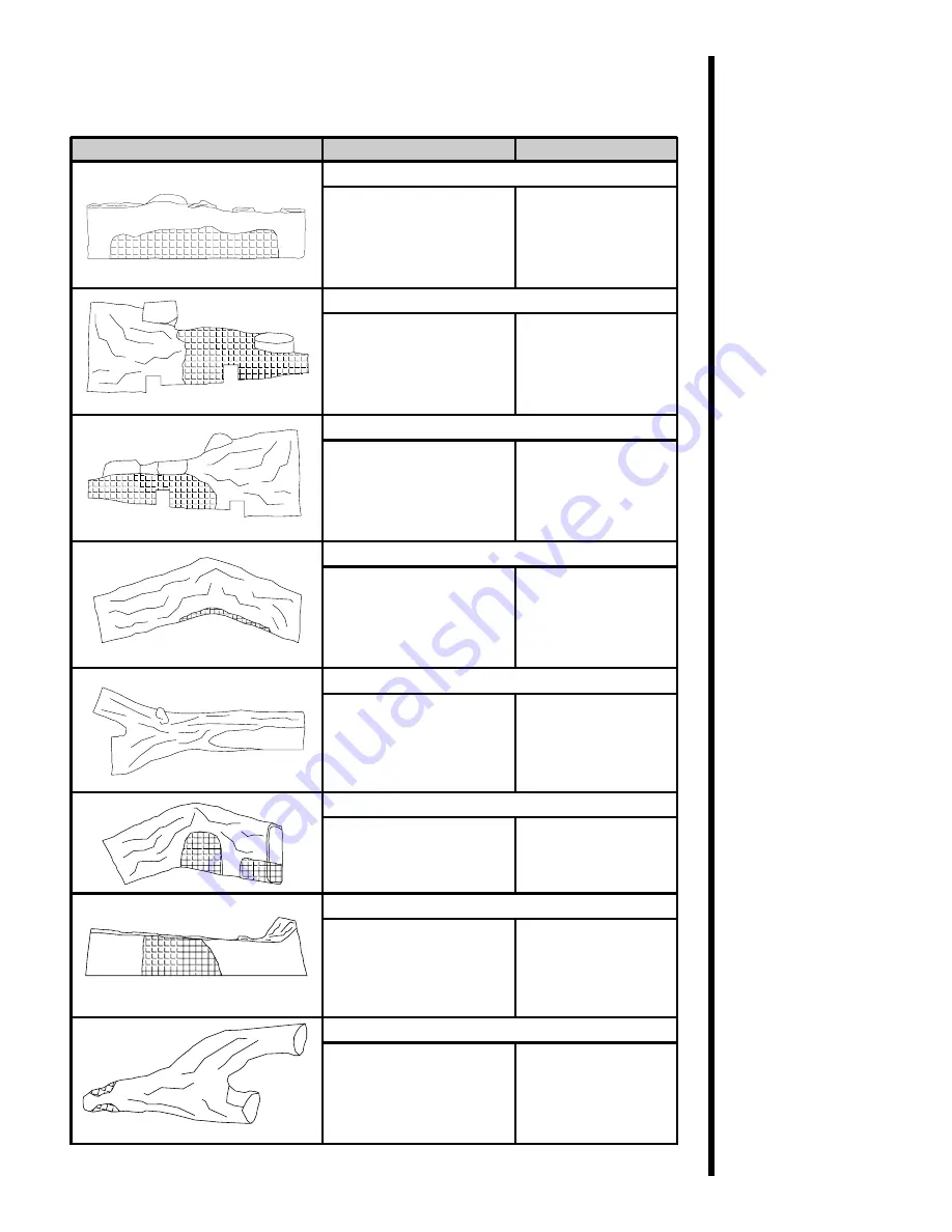
Both Standing Pilot and DSI Ignition (Cont.)
PAR T
PAR T D ESC RIPTION
PAR T NU MB ER
Log #1
SRV582-701
Log #2
SRV582-702
Log #3
SRV582-703
Log #4
SRV582-704
Log #5
SRV582-705
Log #6
SRV582-706
Log #7
SRV582-707
Log #8
SRV402-701
Page 1: ...THE APPLIANCE FOR FUTURE REFERENCE 1 This appliance may be installed in an aftermarket permanently located manufactured mobile home where not prohibited by local codes 2 This appliance is only for us...
Page 2: ...PLACED on or near the appliance Children and adults should be ALERTED to the hazards of high surface temperature and should STAY AWAY to avoid burns or clothing ignition Young children should be CARE...
Page 3: ...Approvals 6 B Installing Vent Components 17 C Vent Termination 23 Step 4 Positioning Leveling and Securing the Fireplace 28 Step 5 The Gas Control Systems 28 Step 6 The Gas Supply Line 29 Step 7 Gas P...
Page 4: ...in the United States or to the CSA C22 1Canadian Electric Code in Canada This model may be installed in a bedroom or bed sitting room in the U S A and Canada High Altitude Installations U L Listed gas...
Page 5: ...gas fireplace and its components are tested and safe when installed in accordance with this Installers Guide Report to your dealer any parts damaged in shipment particularly the condition of the glas...
Page 6: ...g any independent testing laboratory or other party approval of such component part or accessory ANY SUCH ACTION MAY POSSIBLY CAUSE A FIRE HAZARD When planning a fireplace installation it s necessary...
Page 7: ...equirements The top back and sides of the fireplace are defined by stand offs Minimum Clearances from the Fireplace to Combustible Materials Glass Rear of Sides of Top of Front Floor Fireplace Firepla...
Page 8: ...in this manual Step 2 Framing the Fireplace Fireplace framing can be built before or after the fireplace is set in place Framing should be positioned to accommodate wall coverings and fireplace facing...
Page 9: ...l vent runs NO OTHER VENTING SYSTEMS OR COMPONENTS MAY BE USED Detailed installation instructions are included with each vent termination kit and should be used in con junction with this Installers Gu...
Page 10: ...98 mm 8 3 4 222 mm 5 3 4 146 mm NOTE PIPES OVERLAP 1 3 8 INCHES 34 93 mm AT EACH JOINT Figure 5 D Series Direct Vent Component Specifications 5 inch inner pipe 8 5 8 inch outer pipe NOTE TWO 45 ELBOWS...
Page 11: ...NOTE On vertical venting configurations where the vertical component is over 10 feet you may want to install the vertical baffle included in the manual bag assembly to improve flame appearance STRAIGH...
Page 12: ...9 HORIZONTAL VENTING H Kit No Max Run DVK 01D DVK 01TRD 24 610 mm NOTE In a corner installation use two 90 elbows when venting out the rear Figure 7 Corner Installation...
Page 13: ...4mm 6 MAX 1 86m 4 MIN 1 22m 8 MAX 2 4m V H 40 MAX 12 4m H 8 MAX 2 4m NOTE On vertical venting configurations where the vertical component is over 10 feet you may want to install the vertical baffle in...
Page 14: ...40 MAX 12 4MM H 20 MAX 6 2m Figure 9 Venting with One 90 Elbow NOTE IF A 90o ELBOW IS FIRST AT TACHED TO THE UNIT THE MAXIMUM HORIZONTAL RUN IS 3 FEET 914mm NOTE For corner installations A 6 inch 152m...
Page 15: ...MIN 305 mm 2 MAX 610 mm 5 MAX 1 52m 2 MIN 610 mm 4 MAX 1 22 m 10 MAX 3 1m 3 MIN 914 mm 6 MAX 1 86 m 15 MAX 4 65m 4 MIN 1 22 m 8 MAX 2 48 m 20 MAX 6 2m V H H1 40 MAX 12 4 m H 8 MAX 2 48 m H H1 20 MAX...
Page 16: ...O 2 90o ELBOWS V FT H H1 FT 1 MIN 305mm 5 MAX 1 52m 2 MIN 610mm 10 MAX 3 1m 3 MIN 914mm 15 MAX 4 65m 4 MIN 1 22m 20 MAX 6 2m V H H1 40 MAX 12 4m H H1 20 MAX 6 2m V V1 H 40 MAX 12 4m Figure 11 Venting...
Page 17: ...re 12 Venting with Two 90 Elbows 1 MIN 305mm 2 MAX 610mm 2 MIN 610mm 4 MAX 1 22m 3 MIN 914mm 6 MAX 1 86m 4 MIN 1 22m 8 MAX 2 4m 40 MAX 12 4m 8 MAX 2 4m V H H1 H H1 V FT H H1 FT VENTING WITH TWO 2 90o...
Page 18: ...2 4 m H 8 MAX 2 48 m H H1 H2 20 MAX 6 2 m VENTING WITH THREE 3 90 ELBOWS V H H H1 H2 1 MIN 305 mm 2 MAX 610 mm 5 MAX 1 52 m 2 MIN 610 mm 4 MAX 1 22 m 10 MAX 3 1 m 3 MIN 914 mm 6 MAX 1 86 m 15 MAX 4 65...
Page 19: ...5 MAX 4 65m 4 MIN 1 22m 20 MAX 6 2m NOTE H H1 20 MAX 6 2m V V1 H H1 40 MAX 12 4m VENTING WITH THREE 3 90 ELBOWS V FT H H1 FT 1 MIN 305mm 5 MAX 1 52m 2 MIN 610mm 10 MAX 3 1m 3 MIN 914mm 15 MAX 4 65m 4...
Page 20: ...ces of insulation inside the top two starting collars See Figure 15 Remove the heat shield from inside the TOP five inch flue from outside of the firebox WARNING FAILURE TO REMOVE INSULATION IN THE SE...
Page 21: ...eplace collar or previously installed component end with four 4 equally spaced indented sections When the internal beads of each 8 5 8 inch 219 mm outer pipe line up rotate the pipe section clockwise...
Page 22: ...cking each succeeding component into place Figure 17 Adding Venting Components 3 Install Support Brackets For Horizontal Runs The vent system must be supported every five 5 feet of horizontal run by a...
Page 23: ...l brackets to support vertical runs every 8 feet 2 4 m above the fireplace flue outlet Figure 18 Installing Support Brackets 4 Install Firestops For Horizontal Runs Firestops are REQUIRED on both side...
Page 24: ...TOO LONG ADD TO SHIELD IF TOO SHORT EXTERIOR FIRESTOP EXTERIOR FIRESTOP INTERIOR FIRESTOP INTERIOR FIRESTOP HEAT SHIELD Figure 19 12 x 12 Hole and Vent Pipe 2 Position the firestops 3 Place the heat s...
Page 25: ...es sary to accommodate the ceiling joists and or obstructions Cut an 11 inch X 11 inch 280 mm X 280 mm hole through the ceiling using the centerpoint previously marked Frame the hole with framing lumb...
Page 26: ...of the Installing Vent Components section The termination kit should pass through the wall firestops from the exterior of the building Adjust the termination cap to its final exterior position on the...
Page 27: ...ior firestop Figure 24 Round and Trapezoid Termination Caps WARNING THE BOTTOM OF THE VENT TERMINATION CAP MUST BE A MINIMUM OF 12 INCHES 305 MM ABOVE GROUND LEVEL GRADE THE TOP OF THE CAP MUST BE A M...
Page 28: ...ances above grade veranda porch deck or balcony B 12 clearances to window or door that may be opened C 9 U S A clearance to permanently closed window 12 Canada D 18 vertical clearance to ventilated so...
Page 29: ...mber the same size as the roof rafters and install the frame securely Flashing anchored to the frame must withstand heavy winds Continue to install concentric vent sections up through the roof hole fo...
Page 30: ...and snow from the vent system Attach a flashing to the roof using nails and use a non hardening mastic around the edges of the flashing base where it meets the roof Attach a storm collar over the fla...
Page 31: ...NIT IS NOT FOR USE WITH SOLID FUEL Two types of gas control systems are used with this model Standing Pilot Ignition and Direct Spark Ignition DSI Standing Pilot Ignition System This system includes m...
Page 32: ...off valve and a listed flexible gas connector are connected to the 1 2 inch 13 mm inlet of the control valve Locate the gas line access hole in the outer casing of the fireplace Open the fireplace lo...
Page 33: ...disconnected from the gas supply piping system during any pressure testing of the system at test pressures in excess of one half 1 2 psig 3 5 kPa The fireplace must be isolated from the gas supply pip...
Page 34: ...D THE VALVE WILL BE DESTROYED Optional Accessories Optional fan and remote control kits require that 110 120 VAC be wired to the factory installed junction box before the fireplace is permanently inst...
Page 35: ...agram For Direct Spark Ignition DSI Wiring Appliance Requirements This appliance requires that 110 120 VAC be wired to the factory installed junction box Maintain correct polarity when wiring the junc...
Page 36: ...er combustible projections above the top front edge of the fireplace See Figures 2 and 3 for other fireplace clearances Only non combustible materials may be used to cover the black fireplace front Fi...
Page 37: ...h extensions for gas fireplace appliances Installing the Trim Combustible materials may be brought up to the specified clearances on the side and top front edges of the fireplace but MUST NEVER overla...
Page 38: ...ith this gas fireplace The bag labeled Glowing Ember 050 721 is standard glowing ember material To place the ember material Pull the four glass latches out of the groove on the glass frame Remove the...
Page 39: ...the unit Figure 35 GlassAssembly 1 Place the ember material onto the top of the burner Figure 36 Placement of the Ember Material CAUTION IT IS STRONGLY RECOMMENDED THAT TRIM DOORS WITH OPTIONAL MESH S...
Page 40: ...ranties A small amount of air will be in the gas supply lines When first lighting the fireplace it will take a few minutes for the lines to purge themselves of this air Once the purging is complete th...
Page 41: ...ng For more information see Placing Ember Material in the INSTALLERS GUIDE Cleaning Once annually Qualified Brush or vacuum the control Burner Service compartment fireplace logs and Controls Technicia...
Page 42: ...s Figure 38 Pilot Ignitor Flame Patterns MAKE SURE THE FLAMES ARE STEADY NOT LIFTING OR FLOATING STANDING PILOT 3 8 10 mm DSI IGNITION NOTE FLAMES TOO CLOSE TO THE CERAMIC INSULATORS CAN CAUSE NUISANC...
Page 43: ...7 Pilot Orifice NG SRV446 505 Pilot Assembly LP SRV530 511A Pilot Assembly NG SRV530 510A Pilot Tube SRV485 301A 5 Replacement Parts and Accessories All parts listed in this INSTALLERS GUIDE may be or...
Page 44: ...41 DSI Ignition Only PART PART DESCRIPTION PART NUMBER DSI Valve NG LP SRV492 500 SRV492 501 DSI Module SRV501 592 Electrode SRV459 591...
Page 45: ...A DMS LP 49A DMS SRV506 800 SRV65 801 On Off Rocker Switch SRV60 521A Glass Door Assembly GLA 950 Grate Assembly SRV582 360A Burner Tube SRV477 312 Burner SRV582 378A GLASS SPECIFICATIONS 8000TRC 26 1...
Page 46: ...PART DESCRIPTION PART NUMBER Refractory Front SRV582 370 Refractory Right Side SRV582 377 Refractory Left Side SRV582 376 Trim Door DF 950M Log Set Assembly Logs 8TRC Both Standing Pilot and DSI Ignit...
Page 47: ...Standing Pilot and DSI Ignition Cont PART PART DESCRIPTION PART NUMBER Log 1 SRV582 701 Log 2 SRV582 702 Log 3 SRV582 703 Log 4 SRV582 704 Log 5 SRV582 705 Log 6 SRV582 706 Log 7 SRV582 707 Log 8 SRV...
Page 48: ...DESCRIPTION PART NUMBER Fan Kit GFK 160A GFK 230 Remote Control Kit RC SMART SMART STAT RC MLT Wall Switch Kit Off White WSK 21 White WSK 21 W Trim Door Mesh MESH 8TRC Conversion Kit NG Conversion LP...