background image

24

1 1 Frame
2 1 Upright

1 Ramp

Left Pedal Leg

Right Pedal Leg

6 1 Rear 

Stabilizer

Rear Stabilizer Endcap

8 1

Front 

Stabilizer

Front Stabilizer Endcap

10 1 Left 

Pedal

11 1 Right 

Pedal

12 1 Incline 

Motor

13 1 Incline 

Axle

14 1 Pivot 

Axle

15 

1

Left Side Shield

16 

Right Side Shield

17

Console

18 2 Flywheel 

Cover

19 

Arm Axle

20 

Pulse Sensor w/Wire

21 

Right Incline Cover

22 

Left Incline Cover

23 1 Right 

Handlebar

24 

Left Handlebar

25 1 Handlebar 

Cover

26 2 Axle 

Cover

27 

1 “J”-Bolt

28 2 Pedal 

Wheel

29 

4 Wheel 

Bearing

30 2

Frame 

Bushing

31 

2

Upper Body Leg

32 1 “C” 

Magnet

33 

Pedal Leg Cover

34 1 Left 

Crank 

Arm

35 

29.5mm Pulley Spacer

36 

Flywheel

37 1 Magnet
38 1 Pulley/Crank
39 

Control Box Cover

40 1 Control 

Board

41 1 Control 

Box

42 

Lower Wire Harness

43 

Plastic Washer

44 2 Crank 

Bearing

45 1 Idler
46 

2 Foot

47 4 Ramp 

Bushing

48 2 Ramp 

Cover

49 1 Incline 

Sensor

50 1 Sensor 

Cover

51

2

Pedal Leg Bushing

52 1 Resistance 

Motor

53 

Reed Switch Bracket

54 1 Clamp
55 

1 Reed 

Switch/Wire

56 1 Return 

Spring

57 

M10 Split Washer

58 1 Resistance 

Cable

59 1 Flywheel 

Axle

60 2 Flywheel 

Bearing

61 1 Eye 

Bolt

62 1 Adjustment 

Bracket

63 

M10 x 92mm Carriage Bolt

64 2 M6 

Washer

65 

M8 x 63mm Bolt Set

66 2 M8 

Washer

67 

M10 x 60mm Button Bolt

68 2 Handlebar 

Bushing

69

4

M5 x 25mm Screw

70

1

Stop Bolt

71

2

Flywheel Washer

72

1

M10 x 68mm Button Bolt

73

2

Pedal Leg Spacer

74

1

Idler Screw

75

1

Stop Bracket

76

4

M6 x 16mm Patch Screw

77

2

M6 Nut

78

4

M5 x 12mm Bolt

79

4

M5 Washer

80

2

M5 x 6mm Screw

81

6

Upper Body Bushing

82

2

5/16” x 25mm Flange Screw

83

4

M6 x 48mm Flat Head Screw

84

2

Upper Body Grip

85

4

M8 x 42mm Button Bolt

86

6

M8 Nylon Jam Nut

87

2

Upper Body Foam Grip

88

4

M8 Nylon Locknut

89

8

M10 Nylon Locknut

90

2

Sleeve

91

2

Axle Cover Endcap

92

1

Power Socket

93

1

Power Cord

94

4

#8 x 9.5mm Screw

95

1

Upper Wire Harness

96

1

M4 x 16mm Round Head Screw

97

7

M5 x 16mm Screw

98

16

M4 x 16mm Screw

99

2

Ramp Spacer

100

4

M5 Nylon Locknut

101

1

Pulse Extension Wire

102

1

Right Crank Arm

103

1

M6 Nylon Locknut

104

1

Belt

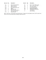
Key No.

Qty.

Description

Key No.

Qty.

Description

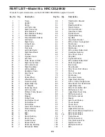
PART LIST—Model No. HRCCEL59930

R0904A

To locate the parts listed below, see the EXPLODED DRAWING on pages 26 and 27.


Summary of Contents for Aire Strider E60 Elliptical

Page 1: ...No HRCCEL59930 Serial No _ Serial Number Decal underneath frame www healthrider com Visit our website at USER S MANUAL QUESTIONS As a manufacturer we are com mitted to providing complete customer satisfaction If you have questions or if there are missing parts please call 1 888 936 4266 Mon Fri 8h00 until 18h30 EST excluding holidays ...

Page 2: ...EMBLY 5 HOW TO USE THE ELLIPTICAL EXERCISER 10 MAINTENANCE AND TROUBLESHOOTING 22 CONDITIONING GUIDELINES 23 PART LIST 24 EXPLODED DRAWING 26 HOW TO ORDER REPLACEMENT PARTS Back Cover LIMITED WARRANTY Back Cover 2 HealthRider is a registered trademark of ICON IP Inc ...

Page 3: ... dismounting or using the elliptical exerciser 10 Keep your back straight when using the ellip tical exerciser do not arch your back 11 If you feel pain or dizziness while exercis ing stop immediately and cool down 12 The pulse sensor is not a medical device Various factors including the user s move ment may affect the accuracy of heart rate readings The pulse sensor is intended only as an exercis...

Page 4: ...ser If you have any questions after reading this manual call our Customer Service Department at 1 888 936 4266 Monday through Friday 8h00 until 18h30 Eastern Time excluding holidays To help us assist you please note the product model number and serial number before calling The model number is HRCCEL59930 The serial number can be found on a decal attached to the elliptical exerciser see the front c...

Page 5: ...s bag check to see if it has been pre assembled M10 x 92mm Carriage Bolt 63 2 M6 Washer 64 2 M10 x 25mm Button Screw 114 3 M8 Washer 66 2 M8 x 19mm Patch Screw 111 2 M6 x 48mm Flat Head Screw 83 4 M8 x 35mm Button Bolt 105 2 M8 x 42mm Button Bolt 85 4 M4 x 16mm Screw 98 4 M10 Nylon Locknut 89 4 M8 Nylon Jam Nut 86 6 M10 Split Washer 57 3 M10 x 105mm Carriage Bolt 115 2 M4 x 16mm Round Head Screw 9...

Page 6: ...Tighten the Patch Screw into one end of the Incline Axle 13 Apply a small amount of grease to the Incline Axle Raise the Ramp 3 Insert the Incline Axle 13 into the welded tube under one side of the Ramp through the motor screw and then into the welded tube under the other side of the Ramp As you insert the Incline Axle through the motor screw make sure that the motor screw does not turn Slide an M...

Page 7: ...4 with two M6 x 48mm Flat Head Screws 83 Note The Left Pedal can be attached in any of three positions using the three sets of holes in the Left Pedal Leg Attach the Right Pedal not shown to the Right Pedal Leg not shown in the same way 6 Hold a Pedal Wheel 28 inside of the bracket on one of the Upper Body Legs 31 Hold the Upper Body Leg and the Pedal Wheel inside of the bracket on the Left Pedal ...

Page 8: ...be on the front of the Upright 2 be careful not to damage the Wires 20 101 Attach the Handlebar Cover with an M4 x 16mm Round Head Screw 96 24 20 101 91 19 86 Tab 105 8 85 96 23 25 2 86 31 Lubricate 7 Apply a small amount of the included Teflon lubricant to a paper towel Rub a thin film of the lubricant onto each Upper Body Leg 31 Identify the Left Upper Body Arm 112 which is marked with an L stic...

Page 9: ... Socket 92 at the rear of the elliptical exerciser 11 Make sure that all parts of the elliptical exerciser are properly tightened Cover the floor beneath the elliptical exerciser to protect the floor from damage Note Some extra hardware may be left over The elliptical exerciser is now fully assembled If you have purchased the optional chest pulse sen sor see page 21 see the instructions below 93 9...

Page 10: ...g an adapter Note When the power cord is plugged in the ellip tical exerciser s incline system may automatically calibrate itself During the calibration process two dashes will appear in the left display of the console and the ramp will move to the highest position and then return to the lowest position The calibration process will last for one to two minutes EXERCISING ON THE ELLIPTICAL EXERCISER...

Page 11: ...hnol ogy Having iFIT com technology is like having a per sonal trainer in your home Using a stereo audio cable available at electronics stores you can connect the elliptical exerciser to your home stereo portable stereo computer or VCR and play special iFIT com CD and video programs iFIT com CDs and videocassettes are available separately iFIT com CD and video programs automatically control the re...

Page 12: ...l show a track representing 440 revolutions a distance of approximately 1 4 mile As you exercise the indicators around the track will light in succession until the entire track is lit The track will then darken and the indicators will again begin to light in succession The Training Zone bar The Training Zone bar will show your pace and the approximate inten sity level of your exercise For exam ple...

Page 13: ... Heart Rate indicator above the right dis play will begin to flash one or two dashes will appear in the right display and then your heart rate will be shown For the most accurate heart rate reading hold the contacts for at least 15 seconds Note If you continue to hold the pulse sensor the right display will show your heart rate for up to 30 seconds The display will then show your heart rate along ...

Page 14: ...shown in the flashing Current Segment column and the resistance of the elliptical exerciser will automatically change to the resistance setting for the second segment Note If all of the indicators in the Current Segment column are lit after the resistance settings have moved to the left the resistance settings will move downward so that only the highest indicators appear in the matrix As you exerc...

Page 15: ...he steps below to use a heart rate program Press any button on the console or begin pedaling to turn on the console See step 1 on page 12 Select one of the heart rate programs When the power is turned on the man ual mode will be selected To select a heart rate pro gram press the Program button repeatedly until P 7 or P 8 appears in the right display During heart rate programs the matrix will displ...

Page 16: ...ng is pro grammed for the next segment Note If the resis tance is too high or too low you can adjust the resistance by pressing the Quick Resistance but tons However when the next segment begins the resistance will automatically change if a different resistance setting is programmed for the next seg ment As you exercise the Training Zone bar will help you to keep your heart rate near the cur rent ...

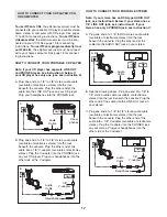
Page 17: ...8 Y adapter available at electronics stores Plug the Y adapter into the PHONES jack on your CD player Plug your headphones into the other side of the Y adapter HOW TO CONNECT YOUR PORTABLE STEREO Note If your stereo has an RCA type AUDIO OUT jack see instruction A below If your stereo has a 1 8 LINE OUT jack see instruction B If your stereo has only a PHONES jack see instruction C A Plug one end o...

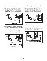
Page 18: ...r into the LINE OUT jack on your stereo HOW TO CONNECT YOUR COMPUTER Note If your computer has a 1 8 LINE OUT jack see instruction A If your computer has only a PHONES jack see instruction B A Plug one end of a 1 8 to 1 8 stereo audio cable available at electronics stores into the jack beneath the console Plug the other end of the cable into the LINE OUT jack on your computer B Plug one end of a 1...

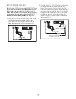
Page 19: ...er end of the cable into the AUDIO OUT jack on your VCR B Plug one end of a 1 8 to RCA stereo audio cable available at electronics stores into the jack beneath the console Plug the other end of the cable into an RCA Y adapter available at electron ics stores Next remove the wire that is currently plugged into the AUDIO OUT jack on your VCR and plug the wire into the unused side of the Y adapter Pl...

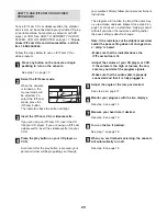
Page 20: ...ed your personal trainer will begin guiding you through your workout Simply follow your personal trainer s instructions The program will function in almost the same way as a resistance and pace program see step 3 on page 14 However an electronic chirping sound will alert you when the resistance setting and or the pace setting is about to change Note If the resistance of the elliptical exerciser an...

Page 21: ...www iFIT com Follow the desired links on our Web site to select a program Read and follow the on line instructions for using a program Follow the on line instructions to start the program When you start the program an on screen count down will begin Return to the elliptical exerciser and begin pedaling When the on screen countdown ends the pro gram will begin The program will function in almost th...

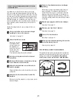
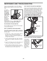
Page 22: ...n of letters and numbers may appear in the dis plays 3 Press the 30 Ramp button The ramp will move all of the way up and then all of the way down 4 Press the Program button three times The con sole will then be in the normal operating mode and the elliptical exerciser will be ready for use HOW TO MOVE THE ELLIPTICAL EXERCISER Stand in front of the elliptical exerciser hold the han dlebars firmly a...

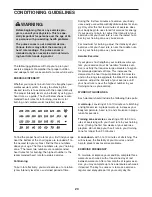
Page 23: ...is to strengthen your cardiovascular sys tem your exercise must be aerobic Aerobic exer cise is activity that requires large amounts of oxygen for prolonged periods of time This increases the demand on the heart to pump blood to the muscles and on the lungs to oxygenate the blood For aerobic exercise adjust the intensity of your exercise until your heart rate is near the highest number in your tra...

Page 24: ...itch Wire 56 1 Return Spring 57 3 M10 Split Washer 58 1 Resistance Cable 59 1 Flywheel Axle 60 2 Flywheel Bearing 61 1 Eye Bolt 62 1 Adjustment Bracket 63 2 M10 x 92mm Carriage Bolt 64 2 M6 Washer 65 2 M8 x 63mm Bolt Set 66 2 M8 Washer 67 2 M10 x 60mm Button Bolt 68 2 Handlebar Bushing 69 4 M5 x 25mm Screw 70 1 Stop Bolt 71 2 Flywheel Washer 72 1 M10 x 68mm Button Bolt 73 2 Pedal Leg Spacer 74 1 I...

Page 25: ...Upper Foam Grip 107 2 Lower Foam Grip 108 1 M4 x 63 5mm Tek Screw 109 2 Wheel 110 4 Wheel Bushing 111 2 M8 x 19mm Patch Screw 112 1 Left Upper Body Arm 113 2 Torque Washer 114 3 M10 x 25mm Button Screw 115 2 M10 x 105 Carriage Bolt 116 2 M4 x 58mm Screw 117 2 Incline Motor Bushing 118 1 Right Upper Body Arm 119 2 Outer Pedal Leg Bushing Allen Wrench User s Manual Key No Qty Description Key No Qty ...

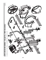
Page 26: ...118 31 90 81 112 90 84 91 91 110 31 110 20 96 86 85 85 86 80 80 105 86 81 81 81 81 81 26 26 84 98 98 110 110 98 98 98 98 98 97 108 97 97 69 69 18 87 114 57 57 114 114 EXPLODED DRAWING Model No HRCCEL59930 R0904A To identify the parts shown below see the PART LIST on pages 24 and 25 ...

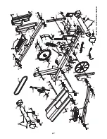
Page 27: ...7 67 89 7 9 65 65 1 111 66 119 51 82 34 102 82 65 65 11 5 51 119 66 111 88 71 60 36 60 59 71 88 61 62 103 83 83 41 97 97 40 94 94 37 98 35 73 43 73 33 33 33 72 89 78 100 52 79 79 58 54 55 97 98 53 22 21 93 89 89 63 115 89 89 116 98 98 98 98 56 77 32 88 45 70 88 27 74 113 113 89 117 117 116 Model No HRCCEL59930 R0904A ...

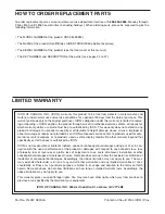
Page 28: ...se improper or abnormal usage or repairs not provided by an ICON authorized service center to products used for com mercial or rental purposes or to products used as store display models No other warranty beyond that specifically set forth above is authorized by ICON ICON is not responsible or liable for indirect special or consequential damages arising out of or in con nection with the use or per...

Reviews: