


A 22 Order No. BA 93-20-290 Issue 01.03.08
19
4.2
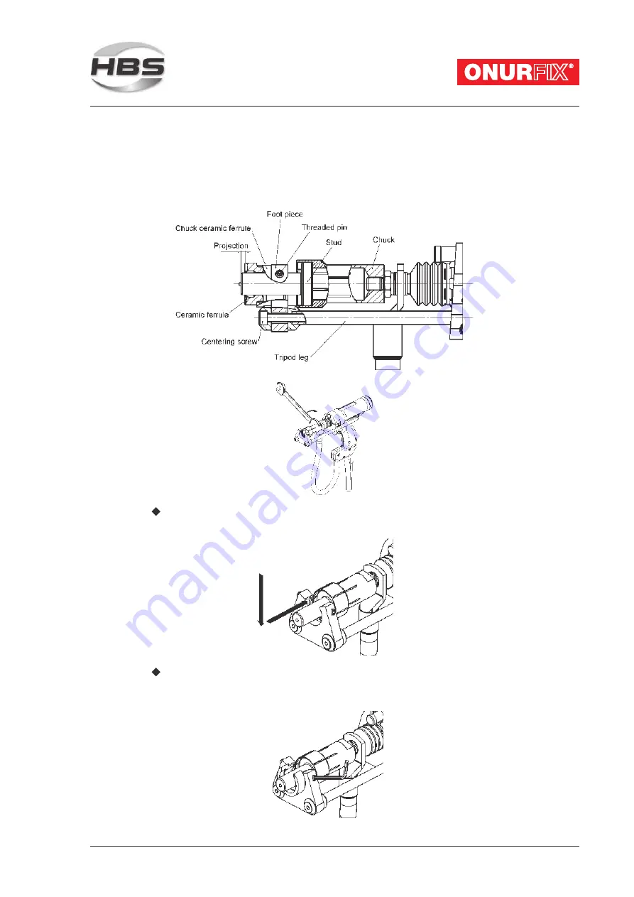
Installation of Chuck and Tripod
Welding with Ceramic Ferrule
Screw the chuck on the thread start of the welding gun and thighten it firmly with
a wrench SW 14/17 (accessory).
Put the stud up to the stop into the chuck.
Attention: The stud must firmly sit in the chuck, otherwise stud and chuck would
burn.
Summary of Contents for 93-20-290
Page 1: ...A 22 Welding Gun 93 20 290 Operating Manual...
Page 45: ...A 22 Order No BA 93 20 290 Issue 01 03 08 45 Welding gun type A 22 ceramic 93 20 290...
Page 60: ...60 A 22 Order No BA 93 20 290 Issue 01 03 08 Service Support...
Page 64: ...64 A 22 Order No BA 93 20 290 Issue 01 03 08...
Page 65: ......