©HBS Bolzenschweiss-Systeme GmbH & Co. KG
All rights reserved – Reprinting, in whole or in part, only with the approval of the manufacturer
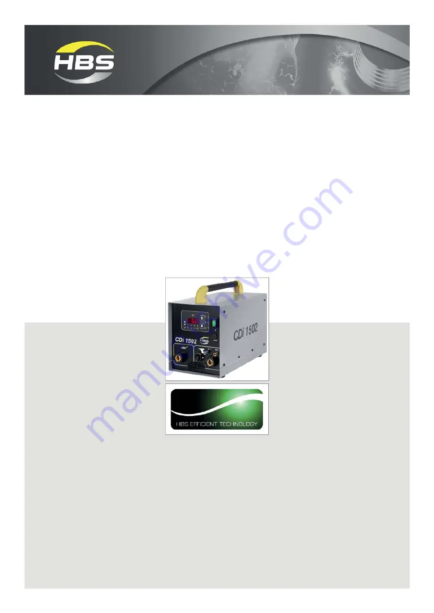
Operating Manual
CDi 1502
Stud Welding Unit
92-10-1504B
2017
Page 1: ...HBS Bolzenschweiss Systeme GmbH Co KG All rights reserved Reprinting in whole or in part only with the approval of the manufacturer Operating Manual CDi 1502 Stud Welding Unit 92 10 1504B 2017...
Page 2: ...om CDi 1502 Operating Manual Issue 2017 01 Order No E BA 92 10 1504B Translation of the Original Operating Manual Please keep the manual in a safe place for future reference Transmission and duplicati...
Page 3: ...your product No claims can therefore be derived from the data illustrations and descriptions We have compiled the data and information in this reference work with the greatest care and have made ever...
Page 4: ...blies 16 8 2 Control Panel and Display 18 8 3 LED Display 20 9 Welding Process 21 9 1 Contact Stud Welding 21 9 2 Gap Stud Welding 24 10 Preparing Workplace and Welding Process 25 10 1 Preparing Surfa...
Page 5: ...ging Voltage for the Welding Gun CI 03 38 12 3 Setting the Charging Voltage 39 12 4 Setting the Stud Feed Time Automatic Mode 39 12 5 Performing the Welding Process 40 13 Checking the Quality of the W...
Page 6: ...ding machine You endanger yourself and others if you operate the stud welding machine incorrectly or fail to observe the safety precautions and warnings This can lead to serious injury or extensive ma...
Page 7: ...elding machine during welding These fields could impact the func tion of heart pacemakers or implanted defibrillators Danger from fumes and airborne particulates Switch on the welding fume extractor a...
Page 8: ...afety helmet when welding above your head Safety shoes Safety goggles with sight glass of protection level 2 in compli ance with the applicable standards and do not look directly into the light arc Re...
Page 9: ...ns or to considerable material damage Caution Problems with the operating procedures can occur if this information is not observed No access for people with active implanted cardiac devices Danger War...
Page 10: ...turer 10 2 Symbols and Terms Used Tip Cross reference to useful information on the use of the stud welding machine Cross references in this operating manual are marked with this symbol or are printed...
Page 11: ...g vol tage into direct voltage Stud feeder Device for automatic feeding of welding elements Stud welding gun Device for welding of welding elements Stud welding machine Stud welding unit including stu...
Page 12: ...ding unit CDi 1502 92 10 1504B 1 Operating manual CDi 1502 E BA 92 10 1504B Inspect the shipment for visible damage and completeness immediately on re ceipt Report any transport damage or missing comp...
Page 13: ...dia 2 and 3 mm Welding material Mild steel stainless steel aluminium and brass Welding rate M3 40 studs min Charging voltage 60 V M8 14 studs min Charging voltage 200 V M8 12 studs min Charging voltag...
Page 14: ...CA 08 CI 03 and PAH 1 as well as the automatic stud feeder VBZ 3 The intended use also implies observance of the operating manual of the compo nent used and compliance with the intervals and conditio...
Page 15: ...afety precautions Use for other than the intended purpose or Transport damage Warranty entitlement shall no longer be valid if modifications changes or service and repair work is carried out by unauth...
Page 16: ...rging de vice 1 Charging of the welding capacitors 3 is performed with the charging device and is fully adjustable The welding capacitors store the energy required for the welding process The quantity...
Page 17: ...ing in whole or in part only with the approval of the manufacturer 8 Components of the Stud Welding Unit Type plate The type plate contains the following information Manufacturer Type Order No Serial...
Page 18: ...following parameters are monitored Deviation from usual charging time Unit temperature Defective thyristor Control discharge relay After the self test the charging voltage last set is shown in the di...
Page 19: ...ng M5 5 mm 5 mm M3 130 24 4 8 suitable for welding M6 6 mm 6 mm M4 170 14 4 8 suitable for welding M8 7 1 mm 7 1 mm M5 220 12 If both arrow keys are pressed simultaneously for approx one se cond 0 3 a...
Page 20: ...if the stud welding unit is overheated After a short cooling period the work can be continued if thyristor is defective in the case of a charging malfunction exceeding the char ging period if arrow ke...
Page 21: ...capacitors of the stud welding unit are discharged Because of the high discharge current the ignition tip evaporates explosion like The air gap between welding element and workpiece is ionized see fi...
Page 22: ...t and the welding element is pressed through the mat up to the workpiece see figure position 1 With ongoing pressure the pressure spring is tensioned until its stop Then the pressure to the welding gu...
Page 23: ...ng element touches the workpiece the arc extinguishes see figure position 4 With high plunging speed the gap closes faster after evaporation of the ignition tip and welding time arc burn time is reduc...
Page 24: ...workpiece is ionized see figure position 3 An arc is pro duced The light arc melts the face of the welding element together with an area of the workpiece of about the same dimension see figure positi...
Page 25: ...ccident preven tion regulations This will help to avoid health damage due to fumes and airborne particu lates Danger from fire and explosion Remove all inflammable materials and liquids from your work...
Page 26: ...welding unit Always place the stud welding unit on a stable level and clean surface Check the condition of all cables and cable connections Have defective cables or their connections immediately repai...
Page 27: ...heck the chuck of your stud welding gun for proper fit and ensure it is tightened Check the bellows of your stud welding gun for damage Check if spring force and lift are set according to the welding...
Page 28: ...e point 10 Preparing Workplace and Welding Pro cess Electric shock hazard Leave the stud welding unit switched off during connection of the connec ting leads In this way you can avoid any unintentiona...
Page 29: ...rrespon ding socket of the stud welding unit Press in the plug and turn it firmly clockwise to the right Connect the control cable Plug the control cable into the corresponding socket of the stud weld...
Page 30: ...the approval of the manufacturer 30 11 Connection 11 2 Connecting the Fully Automatic Stud Feeder VBZ to the Stud Welding Unit Connect the control socket of the feeding unit front side to the control...
Page 31: ...d feeder 2 3 2 Air outlet blue 3 Air outlet black Plug the air connectors of the welding gun into the air outlet bushes at the front of the stud welding unit Observe the color markings black switched...
Page 32: ...set the operating pressure of max 6 bars with the pressure reducing valve of the feeding unit In the filter unit the compressed air is cleaned and drained 11 4 Connecting the Ground Cable Connect the...
Page 33: ...ound clamps Attach the ground clamps to the workpiece as tightly as possible Pay attention to a good contact and symmetrical connec tion The welding point should be in the middle between the two groun...
Page 34: ...an electrician check whether the plug socket to which you intended to connect the stud welding unit is correctly earthed Connect the stud welding unit only to a mains supply with the same mains volta...
Page 35: ...ding unit if you have a heart pacemaker In this case never remain in the vicinity of the stud welding unit during welding Never operate the stud welding unit if persons with heart pacemakers are in th...
Page 36: ...g unit using the arrow keys depends i a on the stud welding gun used the material of the welding element the diameter of the welding element the material of the workpiece Determine the charging voltag...
Page 37: ...4 4 mm 130 26 4 8 suitable for welding M5 5 mm 5 mm M3 190 15 4 8 suitable for welding M6 6 mm 6 mm M4 220 12 4 8 suitable for welding M8 7 1 mm 7 1 mm M5 Material of workpiece Alloyed steel suitable...
Page 38: ...y in combination with welding gun C 08 possible Bi Metallic pins3 Material of welding elements Diameter bush Charging voltage 1 CDi 1502 in V metric in mm Material of workpiece Aluminium AlMg3 6 160 1...
Page 39: ...the stud feeding time blow time for the VBZ and plunger The blow time can be set between 0 25 s and 5 s To do this press the arrow keys twice in quick succession Now set the stud feeding time with th...
Page 40: ...on ductive parts in their vicinity during the welding process These parts are live Never wear metal jewellery even a wristwatch on your body during the welding process This will help to avoid injuries...
Page 41: ...ns Such work may only be carried out by welding specialists Do not carry out such work if you have not been specially trained for it Risk of fire and burns due to glowing weld spatter Wear your person...
Page 42: ...ary Place the welding gun perpendicularly onto the workpiece as soon as the stud welding unit is ready for the welding process Press the welding gun firmly with both hands against the workpiece until...
Page 43: ...not to mix welding elements from different batches Carry out test welds again after a batch change Even the slightest changes to the geometry in particular to the tip of the welding elements require...
Page 44: ...tion Condition Possible cause Corrective actions Good welded joint Low spatters around the weld without outer flaws The weld pool forms a collar around the flange of about 1 1 5 mm Correct parameters...
Page 45: ...ple and as a check for the selected welding parameters The welded joint is stressed by bending in a non defined way 1 Welding element 2 Welded joint Place the bending device on the welding ele ment 1...
Page 46: ...acture in welding element above flange Correct parameters none Fracture in the weld metal Weld energy too low Increase weld energy Plunging speed too low Increase plunging speed Unsuitable stud base m...
Page 47: ...Parameters As first step conduct the tests outlined under points 13 1 and 13 2 As second step optimise the welding parameters according to the table under point 12 2 Determining the Charging Voltage O...
Page 48: ...edge of a workpiece a blowing effect can occur This is an undesirable deflection of the light arc This results in uneven melting of the stud material in increased poring and undercuts in the welding...
Page 49: ...of the stud welding unit Qualified specialists Leads interrupted Check leads Replace leads Qualified specialists No display No ground connection Check ground connec tion on workpiece Tighten ground co...
Page 50: ...r service department Trained personnel Continuously red display Elt Charging time of capacitor battery too long Switch off stud welding unit then switch on after some seconds if the stud welding unit...
Page 51: ...Modify set parameters Trained personnel Short circuit of sole noid circuit of the gun Check resistance value at control cable connec tor 18 to 22 bet ween Pin 1 and Pin 2 Replace control cable connect...
Page 52: ...the approval of the manufacturer 52 15 Shutting Down 15 Shutting Down Switch off the stud welding unit Pull out the mains plug Disconnect the control cable and welding cables from the stud welding uni...
Page 53: ...onnel Carry out only the work described here on your stud welding unit Repairs may only be carried out by appropriately qualified personnel Inform your dealer or your maintenance department 16 1 Clean...
Page 54: ...ndition of the mains cable Inform your dealer or maintenance department if you discover any dama ge Check whether the readings on the display of the stud welding unit are still legible before starting...
Page 55: ...ocation when not in use Protect the stud welding unit from moisture and metallic contamination Store the stud welding unit only under the following ambient conditions Storage temperature 5 C to 50 C R...
Page 56: ...t of this declaration The product is conform with following further EU Directives including changes to the Directives to be applied at the moment of this declaration Low voltage guideline 2014 35 EU E...
Page 57: ...tor Detailed descriptions of errors Service Support may be done up to the value of EUR without quotation Yes No Could you find any damage burn marks on the cables Yes No on chucks Yes No Are all plug...
Page 58: ...l 55 E ear protection 9 electrical hazards 9 electromagnetic fields 9 35 F fire extinguisher 7 41 fire extinguisher approved 25 fire hazard 7 form Service Support 51 57 full ear hearing protection 8 f...
Page 59: ...der 11 stud feeding time 39 stud welding gun 11 stud welding machine 11 stud welding unit 11 substances explosive 25 surface of base material 46 surface of welding element 46 switch on the stud weldin...
Page 60: ...HBS Bolzenschweiss Systeme GmbH Co KG All rights reserved full or partial reproduction subject to prior approval of the manufacturer 60...
Page 61: ......
Page 62: ...HBS Bolzenschweiss Systeme GmbH Co KG Felix Wankel Strasse 18 85221 DACHAU GERMANY Phone 49 8131 511 0 Fax 49 8131 511 100 E mail post hbs info com www hbs info com...