Interface description
38
A02590_04_E00_00
HBM: public
TIM40
13.1.2
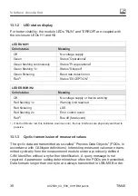
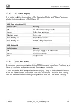
LED status display
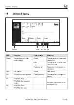
For better visibility, the module LEDs ”RUN” and ”ERROR” are coupled with
the enclosure LEDs H1 and H2.
LED RUN/H1
Color/status
Meaning
Off
No voltage supply
Green
Status ”Operational”
Green flashing continuously
Status ”Pre‐operational”
Green flashing 1x
Status ”Stopped”
Green flickering
Baud rate detection on
Red
Status ”EXCEPTION”
LED ERROR/H2
Color/status
Meaning
Off
No voltage supply or device working
Red flashing 1x
Warning limit reached
Red flickering
LSS
Red flashing 2x
Error control event
Red
Bus off (fatal event)
1)
If both LEDs are red, this indicates a serious error, the bus interfaces are physically switched to
passive.
13.1.3
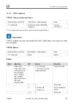
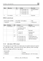
Cyclic transmission of measured values
The cyclic data are transmitted as so‐called ”Process Data Objects” (PDOs, in
accordance with CANopen definitions). Interesting measured values are trans
mitted cyclically from the measurement module under a previously defined
CAN Identifier, without any further identification. A query message is not
required. A parameter setting determines how often the PDOs are transmitted.
Data formats longer than one byte are always transmitted in LSB–MSB order.

