22
3. Prior to Operation
Always ensure tools are used,
inspected and maintained in
compliance with the respective
local, state, national or federal
regulations.
• Before starting to work, disconnect engine
from power supply. Carefully read operating
instructions for the engine and if necessary for
the other equipment assemblies and devices
(e.g. radio etc.)
ATTENTION
Ensure that the radio code is recorded.
CAUTION
Jacked up vehicles must be secured
adequately
ATTENTION
Only use appropriate spare parts.
4. Operation
Engine Timing Applications
Petrol / Diesel Engines
AUDI – SEAT – SKODA – VOLKSWAGEN
4.1 Petrol Engines
1.2 6v. and 12v. engines (Chain Drive)
1.4 / 1.6 16v. FSi engines (Chain Drive)
4.2 Diesel Engines
Pumpe Duse (Unit Injection) engines
4.3 Cross Reference
to VAG Tool Numbers (see page 21)
4.1 PETROL ENGINES
1.2 6v. and 12v. Petrol Engines (Chain Drive)
and
1.4 / 1.6 16v. FSi Engines (Chain Drive)
1.2 6v. and 12v. Petrol Engines (Chain Drive)
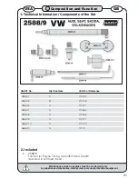
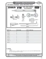
Use HAZET 2588-14 and 2588-15 Camshaft
Setting Tools and HAZET 2588-16 Flywheel
Locking Pin
For model usage / engine codes refer to
Application Chart, page 6
The VAG 1.2 engine range can be a single
camshaft 6 valve variant (AWY/BMD) or twin
camshaft 12 valve engines (AZQ/BME)
.
•
•
•
•
•
Checking valve timing
Figure 1 , Page 3
Camshaft Setting Tool 2588-14 (single
camshaft engines)
HAZET 2588-14 enters through the top of the
engine to locate the camshaft timing ‘slot’.
Remove the air cleaner, Hall sender unit and
engine speed sensor.
Turn the crankshaft, in the normal direction of
rotation, so that the ‘slot’ in the camshaft is seen
in the hole for the Hall sender unit.
Insert HAZET 2588-14 Camshaft Setting Tool,
and secure in place with a M6 bolt.
Figure 2 , Page 3
Camshaft Setting Tools 2588-15 (x2) (twin
camshaft engines)
Similar procedures to the single camshaft
engines except the 2 x HAZET 2588-15
Camshaft Setting Tools enter ‘timing slots’ at
the
rear
of the camshafts.
Remove the air cleaner and both covers at the
rear camshaft ends.
Remove the engine speed sensor and turn the
crankshaft so that the ‘timing slots’ in the rear of
camshafts are horizontal.
Insert HAZET 2588-15 Tools into the ‘timing
slots’ and secured in place with M6 bolts.
Crankshaft timing
Figure 3 , Page 3
Flywheel (Crankshaft) Locking Pin 2588-16
(single & twin camshaft engines)
The crankshaft is locked in timed position by
inserting HAZET 2588-16 Pin into the flywheel
timing hole.
Valve Timing Adjustment
Single Camshaft engines:-
If it is not possible to insert both the Camshaft
Setting Tool and the Flywheel Locking Pin with
ease, the timing can be adjusted by positioning
the ‘timing slot’ in the camshaft so it is visible
in the hole for the Hall sender unit and by
inserting HAZET 2588-14 Tool. Then, using a
suitable sprocket counter-holding tool, hold the
camshaft sprocket and slacken its bolt. Turn
the crankshaft, in direction of normal engine
rotation, until HAZET 2588-16 Pin can be
inserted correctly into the flywheel.
Counter-hold the camshaft sprocket and tighten
the sprocket bolt.
•
•
•
•
•
•
•
•
•
•
•
ê
ê
USA
GB
3
Composition and Function
Maintenance work on engines must be carried out only
by experienced mechanics. Always wear personal protective equipment.


