background image

34

6. APPENDIX (continued)

ENPI11M

1

2

3

4

6

5

8

7

10

9

11

12

26 25 24

23

22

21

20

19

18

17

16

15

14

13

29

28

27

30

31

32

33

34

35

36

37

38

39

Summary of Contents for ENERGYLINE PRO INVERTER

Page 1: ...ENERGYLINE PRO INVERTER ISENPINV_RevB SWIMMING POOL HEAT PUMP UNIT Installation Instruction Manual ...

Page 2: ...itial start up 11 3 6 Water flow setting 13 4 USER INTERFACE 14 4 1 General presentation 14 4 2 Setting the Date and Time 15 4 3 Timer function settings 15 4 4 Setting and visualisation of the set point 17 4 5 Locking and unlocking the touch screen 18 4 6 SILENT function settings 19 5 MAINTENANCE AND WINTERISING 22 5 1 Maintenance 22 5 2 Winterising 22 6 APPENDIX 24 6 1 Electrical diagrams 24 6 2 ...

Page 3: ...l keep it for future usage Authorised personnel The installation electrical connections maintenance and repairs of the device must be carried out by an accredited professional in accordance with the regulatory texts and the rules of the art in effect in the country where the device is installed see 3 4 For any intervention on the cooling circuit the professional must hold a certificate of competen...

Page 4: ...y the grounding connection of the device and its continuity Clean the coil with the help of a soft brush or jet of air or water Warning never use a high pressure cleaner Verify that the drains flow well Verify the tightening of the hydraulic and electrical connections Verify the hydraulic sealing of the condenser Have the leak tightness of the cooling circuit to the leak detector checked by an acc...

Page 5: ...gas R410A This product contains greenhouse effect fluorinated gases covered by the Kyoto protocol GWP Value 1 2088 Value based on the 4th GIEC report Any intervention on the cooling circuit must be carried out by an accredited professional as mentioned hereinabove Periodic inspections for refrigerant leakage can be required as a function of European or local legislation Please contact your local d...

Page 6: ...l water flow a m3 h 3 20 4 00 4 70 5 70 Water pressure drop max kPa 4 60 7 00 11 60 5 10 Compressor Rotary Type Inverter Quantity 1 Refrigerant R410A Weight of refrigerent kg 1 10 1 30 1 80 2 10 teqCO2 2 30 2 71 3 76 4 38 Leak control frequency Not compulsory but recommended Fan Axial Diameter mm 500 Quantity 1 1 2 2 Motor Inverter Quantity 1 1 2 2 Rotation speed Tr min 500 750 500 900 400 800 400...

Page 7: ...7 C 43 C Water temperature 12 C 40 C 8 C 40 C Relative humidity 80 80 Setting range from the set point 15 C 32 C 8 C 32 C If the temperature or humidity does not correspond to these conditions the security measures could be activated and the swimming pool heat pump unit may no longer work The maximum heating temperature is set at 32 C to prevent damage to the liners Hayward cannot be held responsi...

Page 8: ...sions Models C C F G H D E A A B B D E ENPI7M ENPI9M ENPI11M ENPI13T Water outlet Ø 50 mm Water inlet Ø 50 mm Unit mm TYPE SIZE ENPI7M ENPI9M ENPI11M ENPI13T A 1150 1150 B 485 485 C 868 1275 D 400 470 E 100 98 F 815 790 G 447 447 H 430 430 ...

Page 9: ... Choose a location that is preferably sunlit and sheltered from dominant winds The device must be perfectly accessible for later installation and maintenance work Placed under a shelter the minimum required distances mentioned below must be respected in order to avoid any risk of air recirculation and a deficiency in the unit s overall performance Water Inlet valve Water outlet valve Filter By pas...

Page 10: ... Fasten the device in compliance with the tightening indicated to avoid any risk of accident or damage to equipment and persons Another possibility install the heat pump on rubber floor supports using suitable fastenings not supplied x 4 5 7 N m The maximum installation distance between the unit and the swimming pool is 15 metres The total length of the piping to and from the unit is 30 metres Ins...

Page 11: ...s valve between the heat pump entrance and exit If an automatic distributor or an electrolyser is used it should be installed imperatively after the heat pump with the goal of protecting the titanium condenser against an elevated concentration of chemicals Be sure to install the by pass valve and the supplied union connections at the water inlet and outlet level in order to simplify purging during...

Page 12: ...LATION AND CONNECTION continued 3 4 Electrical connection F NF C15 100 GB BS7671 1992 D DIN VDE 0100 702 EW EVHS HD 384 7 702 A ÖVE 8001 4 702 H MSZ 2364 702 1994 MSZ 10 553 1 1990 E UNE 20460 7 702 1993 RECBT ITC BT 31 2002 M MSA HD 384 7 702 S2 IRL Wiring Rules IS HD 384 7 702 PL PN IEC 60364 7 702 1999 I CEI 64 8 7 CZ CSN 33 2000 7 702 LUX 384 7 702 S2 SK STN 33 2000 7 702 NL NEN 1010 7 702 SLO...

Page 13: ...y see the troubleshooting guide see 6 4 3 INSTALLATION AND CONNECTION continued Never use an electrical plug for the power supply The electrical power supply must have in a suitable manner an omnipolar protection device of the D curve circuit breaker type as well as a 30mA protection differential circuit breaker see following table Use an RO 2V R 2V or equivalent power cord The cables sections are...

Page 14: ...estart as long as the pool pump is running if the pool temperature is at least 0 5 C below the set temperature Water flow switch The unit is equipped with a flow switch that turns on the heat pump when the pool filtration pump is running and deactivates it when the filtration pump is out of order If the water is low the E03 alarm code will appear on the regulator See 6 4 Time delay The unit is equ...

Page 15: ...ure see principle diagram 3 1 You can verify the switch by seeing the entry exit temperatures directly on the control panel 3 INSTALLATION AND CONNECTION continued Water inlet temperature Water outlet temperature Note Opening the by pass valve creates a weaker flow which leads to an increase in T Closing the by pass valve creates a stronger flow which leads to a decrease in T ...

Page 16: ...creen 3 Date 4 Hour 5 Outside temperature 6 Recording base Water temperature and power consumption 7 Reading settings and saving 8 Scroll up Increase 9 Scroll down Decrease 10 Operating mode selection 10a Cooling mode 10b Heating mode 10c Automatic mode 11 Water Output temperature 12 Selecting silence mode 12a Setting silence mode timer 12b Silence mode and activation light 13 Conversion C F 14 Wa...

Page 17: ...sary if you would like to run the heat pump for a shorter period than what is defined by the filtration clock Therefore you can program a deferred start and an anticipated stop or simply stop a certain timeframe from running at night for example It is possible to set one Start Timer and one Stop Timers 1 2 4 3 Quit without saving Back to the previous screen Back Confirm Enter all the fields Day Mo...

Page 18: ...ng Repeat steps 3 to 6 to set and activate the stop time When the settings are complete the operating range of the heat pump is highlighted in green and the highlight range is yellow Press twice on to return to the main screen 6 3 4 5 1 2 Stop Confirm Activate Start Blue highlighting Activated Grey Deactivated The setting step is hour to hour ...

Page 19: ...r Mode ON Press the button to display the set point then press or pour to set the set point you wish Confirm by pressing and you will return to the main screen automatically The setting is made with a precision of 0 5 C It is recommended to never exceed 30 C to avoid alteration of the liners ...

Page 20: ...ore the screen locks automatically to between 1 and 10 minutes or simply to cancel this function 1 2 4 5 3 Automatic locking activated To unlock the screen press anywhere on the screen for 2s Enter the code 22 and confirm by pressing 2 1 3 Set the time to between 1 and 10 minutes Saving is automatic 4 Press twice to return to the main screen 5 To deactivate automatic locking press ...

Page 21: ...ables the heat pump to be used in economic and very silent mode when the heating needs are low maintaining the pool temperature or need for ultra silent operation This function can be Activated Deactivated manually or using a Timer Manual Activation Silence mode activated 1 2 ...

Page 22: ...20 4 USER INTERFACE continued Manual Deactivation Setting the Timer 1 2 Silence mode deactivated 1 2 ...

Page 23: ... hour to hour Once the Timer is activated it is active 7 days a week Setting the Timer continued 1 2 5 4 3 Confirm 1 Start time input and confirmation 2 End time input and confirmation 3 Confirm 4 Activation 5 Deactivation 6 Back to the main screen 6 ...

Page 24: ... that the drains flow well Verify the tightening of the hydraulic and electrical connections Verify the hydraulic sealing of the condenser Have the leak tightness of the cooling circuit to the leak detector checked by an accredited professional Before any maintenance operation the heating pump must be disconnected from any electrical current source The maintenance operations must only be carried o...

Page 25: ...23 Page left intentionally blank ...

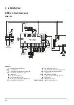
Page 26: ... 1 3 2 4 5 6 7 8 01 K2 1 2 N N N N FM ET ET YEL BLK WHT RED 4 Controller YEL 485B BLK GND RED 12V WHT 485A CON2 L K2 N K2 L N RED BLU RED BLK WHT t 50K EP ET EP EP 1 2 3 4 1 4 4 Pressure sensor PS Remote ON OFF 6 8K 220 240V 50Hz TO POWER SUPPLY Dry Contact 16A max REMARKS AT AIR TEMPERATURE SENSOR LP LOW PRESSURE SWITCH COMP COMPRESSOR OT OUTLET WATER TEMPERATURE SENSOR CT EVAPORATOR TEMPERATURE ...

Page 27: ...OUT2 OUT3 AC N1 OUT4 OUT5 485A1 12V CN2 12V 5V 0 10V OUT PWM OUT AI12 AI DI11 AI DI10 AI DI09 PWM IN AI DI08 AI DI07 AI DI06 AI DI05 AI DI04 AI DI03 AI DI02 AI DI01 0 5V IN 485A2 12V CN8 485B2 GND GND GND GND GND GND GND GND GND GND GND GND GND GND GND GND GND GND GND L N A B GND12V YEL RED BLK COMP U V W U W V L N L N 1 2 L N N EEV 5 4V FS FS FS LP LP HP HP LP HP t 5K SUT SUT SUT t 5K IT IT IT t ...

Page 28: ...UT3 OUT4 OUT5 R485A1 12V CN2 12V 5V 0 10V OUT PWM OUT AI12 AI DI11 AI DI10 AI DI09 PWM IN AI DI08 AI DI07 AI DI06 AI DI05 AI DI04 AI DI03 AI DI02 AI DI01 0 5V IN R485A2 12V CN8 R485B2 GND GND GND GND GND GND GND GND GND GND GND GND GND GND GND GND GND GND GND L N A B GND12V YEL RED BLK COMP U V W U W V L N L N 1 2 L N N EEV 5 4V FS FS FS LP LP HP HP LP HP t 5K SUT SUT SUT t 5K IT IT IT t 5K OT OT ...

Page 29: ...I06 AI DI05 AI DI04 AI DI03 AI DI02 AI DI01 0 5V IN 485A2 12V CN8 485B2 GND GND GND GND GND GND GND GND GND GND GND GND GND GND GND GND GND GND GND R FS FS FS LP LP HP HP LP HP t 5K IT IT IT t 5K OT OT OT CT CT t 5K CT AT AT t 5K AT N 4V 1 3 2 4 5 6 7 8 01 ET YEL BLK WHT RED R t 50K 4 ET ET SUT SUT SUT t 5K EEV 5 R S T N RED BLK WHT BLU N N N R R Remote ON OFF A B GND 12V COMP U V W U W V L3 L2 L1...

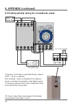
Page 30: ...rity Wire terminals 1 and 2 as indicated in the diagram above to activate the operation of the filtration pump in 2 minute cycles each hour if the temperature of the pool is lower than the set point Never connect the power supply of the filtration pump directly to terminals 1 and 2 Power supply 230V 50Hz Monophasic pump Dry contact 16 A max OUT2 ...

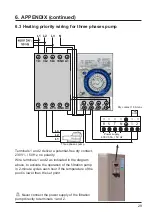
Page 31: ...tact 16 A max Terminals 1 and 2 deliver a potential free dry contact 230V 50 Hz no polarity Wire terminals 1 and 2 as indicated in the diagram above to activate the operation of the filtration pump in 2 minute cycles each hour if the temperature of the pool is lower than the set point Never connect the power supply of the filtration pump directly to terminals 1 and 2 6 APPENDIX continued OUT2 ...

Page 32: ...30 6 APPENDIX continued 6 4 Exploded view and spare parts ENPI7M A 17 18 19 20 21 22 23 35 24 25 29 30 31 32 28 33 34 26 27 1 2 3 16 15 14 13 12 11 10 9 8 7 6 5 4 A ...

Page 33: ... 9 HWX32008220008 Black electric access hatch 36 HWX20003242 Coil air water temp sensor 10 HWX20000110217 Inverter DC compressor 37 HWX20003223 Compressor sensor 50 kΩ 11 HWX32009210389 Right panel 38 HWX20000240216 Wintering cover 12 HWX200036005 Flow switch 13 HWX32018210127 Top cover 14 HWX32009120046 Coil 15 HWX32018210115 Electrical box cover 16 HWX32018210114 Support panel 17 HWX32009210391 ...

Page 34: ...32 6 APPENDIX continued ENPI9M 21 20 19 18 17 A 22 23 24 25 26 27 28 34 38 39 33 30 29 32 37 36 35 31 1 2 3 4 5 16 15 14 13 12 11 10 9 8 7 6 A ...

Page 35: ...cal box 10 HWX20011499 Check valve 35 HWX20003909 2 point terminal block 11 HWX20011491 4 ways valve 36 HWX20000360297 Relay 12 HWX20000140450 Electronic expansion valve 37 HWX40003901 Terminal block 5 connections 13 HWX32008220008 Black electric access hatch 38 HWX32009220085 Right decorative panel 14 HWX20000110289 Inverter DC compressor 39 HWX32009220083 Front panel 15 HWX32018210121 Right pane...

Page 36: ...34 6 APPENDIX continued ENPI11M 1 2 3 4 6 5 8 7 10 9 11 12 26 25 24 23 22 21 20 19 18 17 16 15 14 13 29 28 27 30 31 32 33 34 35 36 37 38 39 ...

Page 37: ...port panel 35 HWX40003901 Terminal block 5 connections 11 HWX32018210127 Black ABS upper panel 36 HWX20000360297 Relay 12 HWX32019210071 Electrical box cover 37 HWX20003909 2 point terminal block 13 HWX32019210123 Centre wall 38 HWX26300069 Colour touchscreen 14 HWX32019210072 Electrical box 39 HWX20000230596 HAYWARD logo 15 HWX200036005 Flow switch 40 HWX20003242 Coil air water temp sensor 16 HWX...

Page 38: ...36 6 APPENDIX continued ENPI13T 1 2 3 5 7 6 9 8 11 10 12 16 13 14 17 18 19 20 22 21 24 26 25 27 29 32 30 33 34 35 36 37 43 42 38 39 40 15 46 47 44 45 23 28 31 4 41 ...

Page 39: ...X95053156904 PCB Board 13 HWX32019210071 Electrical box cover 38 HWX20000390180 Terminal block 5 connections 14 HWX32015210026 Centre wall 39 HWX20000360297 Relay 15 HWX32019210105 Horizontal electrical box 40 HWX20003909 2 point terminal block 16 HWX32019210098 Vertical electrical box 41 HWX20000390049 MSB terminal 2 5 F 17 HWX200036005 Flow switch 42 HWX20000390048 MSDB terminal 2 5 M 18 HWX3200...

Page 40: ...lled automatically and the triangle changes to solid grey To delete the error list press on then return to the previous screen by pressing on If there is a fault on the heat pump the symbol appears blinking red in the left hand corner of the screen Press the symbol to access the list of errors Refer to following table Error codes Description Date and time of appearance ...

Page 41: ...rcuited Check the AI DI03 connections on the card or replace the sensor Large coolant leak search for the leak with the detector Air flow too low check the ventilator rotation speed Check the evaporator is not clogged clean its surface Flow sensor fault E03 The sensor is open or has short circuited Check the AI DI02 connections on the card or replace the sensor Lack of water check the filtration p...

Page 42: ...ress on to access the history of water input and output temperature recordings This data is available for 60 days Press on to access the average electric power consumed Water input temperature curve Water output temperature curve Press on to return to the main screen ...

Page 43: ...terms of the warranty and request the repair or replacement of an item No equipment returned to our factory will be accepted without our prior written agreement Worn parts are not covered by the warranty 6 8 End of life of the device The symbol of the crossed out dustbin concerning the treatment and the reclamation of electrical and electronic waste means that the products must not be disposed of ...

Page 44: ...42 Page left intentionally blank ...

Reviews: