Hawksley 01400-00, Instruction Manual
The Hawksley 01400-00 is a versatile product that requires an Instruction Manual to operate effectively. You can download the manual for free from manualshive.com, ensuring that you have all the information you need to make the most of your purchase. Get your copy today and start using your Hawksley 01400-00 with confidence.
Share
Download


Reviews:
No comments
Related manuals for 01400-00

FX-ARM CONTROLLER
Brand: Magicfx Pages: 16

24950
Brand: Oemtools Pages: 4

A12
Brand: JB-Lighting Pages: 60

WJHD309 - DIGITAL DISK RECORDER
Brand: Panasonic Pages: 7

WJ-ND300 Administrator Console
Brand: Panasonic Pages: 24

45135
Brand: FJC Pages: 2

P4
Brand: JB-Lighting Pages: 60

Aspect Q-CARD 100-4T
Brand: idi Pages: 38

IG2
Brand: rbd instruments Pages: 18

Perfusor Space
Brand: B. Braun Pages: 40

Perfusor Space
Brand: B. Braun Pages: 4

TLR5200
Brand: Tieline Pages: 359

F12-152 Series
Brand: Parker Pages: 24

SeQual Eclipse 5
Brand: CAIRE Pages: 2
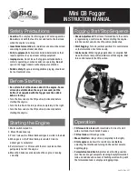
Mini DB
Brand: B&G Pages: 2

NEB-LSP-0007
Brand: NEBO Pages: 2

PowerAdapt
Brand: Grundfos Pages: 43

SciCan STATIM 2000S
Brand: Coltene Pages: 45


