background image

Cable Management

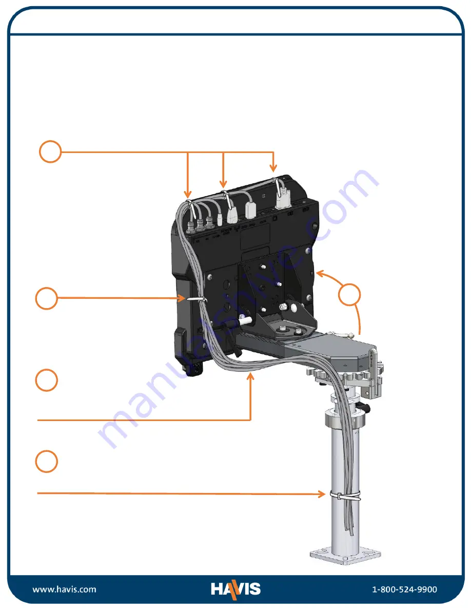
1) Orient the Docking Station in a position that is comfortable to work with.
2) Install all cables that are necessary for computing needs.
3) Use Zip Ties (Hardware Kit Item 1) to strain relieve cables to the Strain Relief Points, routing all cables 

together to the front of the Docking Station.

4) Secure cable bundle to the Mounting Bracket with a supplied Zip Tie. 
5) Create a service loop with cable bundle to ensure that no tension is on the connectors and to enable 

intended motion.

6) Tie off cables onto a stationary part of the mounting system.

(Mounting system not included with Docking Station)

4

5

This loop must be large enough to allow 
full range of expected rotation and 
extension without stressing connections.

Collect cables to secure to the
mounting system.

(Note: mounting system not included)

1

Use as many Zip Ties as

necessary to secure cables.

2

3

Summary of Contents for DS-DELL-420 Series

Page 1: ...Notebooks DS DELL 420 Series DS DELL 421 DS DELL 421 3 DS DELL 422 DS DELL 422 3 DS DELL 423 DS DELL 423 3 DS DELL 425 DS DELL 425 3 DS DELL 426 DS DELL 426 3 DS DELL 428 DS DELL 428 3 DS DELL 420 SERIES_OMN_1 22 Havis Inc 75 Jacksonville Road Warminster PA 18974 ...

Page 2: ...DS DELL 425 3 DS DELL 426 DS DELL 426 3 DOCKING STATIONS DO NOT CONNECT DIRECTLY TO VEHICLE VOLTAGE SOURCE This product requires a certified automotive grade Dell approved 90W power source rated for a continuous regulated 19 5VDC output Havis Part Number LPS 137 or equivalent Failure to comply with this requirement will cause product damage that is NOT repairable and is NOT covered under warranty ...

Page 3: ...haracters which describe product options Product Options This declaration covers all options of the above product which bear the CE Marking Is in conformity with the following standards or other normative documents Automotive EMC Directive EN 50498 2010 Electromagnetic compatibility EMC 2004 108 EC Product family standard for aftermarket electronic equipment in vehicles Directive 2011 65 EU Restri...

Page 4: ...Specifications 12 40 314 80 mm 10 60 269 10 mm 2 73 69 40 mm 4 80 121 74 mm Dock Centerline 3 0 Havis Mounting Pattern ...

Page 5: ... Docking Station Mounting Bracket Latch Hook Release Handle Rear Fences Front Hook Release Buttons and Lockout Holes Front Hooks Strain Relief Points Locator Posts Docking Connector Barrel Lock Latch Release Buttons ...

Page 6: ...llation 5 32 Hex Drive For attaching Mounting Bracket to Motion Device with Button Head 20 Screws 3 Phillips Drive For attaching Docking Station to Mounting Bracket with Pan Head 20 Screws T10 Torx Drive For 12mm long Lockout Screws j Antenna Identification DS DELL 421 3 DS DELL 422 3 DS DELL 423 3 DS DELL 425 3 DS DELL 426 3 DS DELL 428 3 A WIFI B GPS C CELLULAR Rearward Facing Antenna Connectors...

Page 7: ...L 425 3 DS DELL 426 DS DELL 426 3 Rearward Facing Ports Advanced Port Replication DS DELL 421 DS DELL 421 3 DS DELL 422 DS DELL 422 3 USB 2 0 Green LED Indicator Docked Mic Speaker Ethernet RJ45 Gigabit LAN 10 100 1000 MB USB 3 0 x3 Serial x2 Antenna TNC Optional Part IDs DS DELL 421 3 DS DELL 422 3 Power Input VGA HDMI ...

Page 8: ... continued Rearward Facing Ports Basic Port Replication DS DELL 425 DS DELL 425 3 DS DELL 426 DS DELL 426 3 USB 3 0 x3 Antenna TNC Optional Part IDs DS DELL 425 3 DS DELL 426 3 Power Input Ethernet RJ45 Gigabit LAN 10 100 1000 MB ...

Page 9: ...ket will accommodate Havis Motion Devices as well as most competitors NOTE We recommend applying a drop of medium strength blue thread locking adhesive to the threads of all fasteners 2 Lower the Docking Station to the Mounting Bracket as shown and secure with 4 1 4 20 x 3 8 long pan head screws Hardware Kit Item 5 Torque screws to 80 in lbs 9 0Nm 10 1 4 20 x 3 8 Pan Head Screws 1 4 20 x 5 8 Butto...

Page 10: ...e Mounting Bracket with a supplied Zip Tie 5 Create a service loop with cable bundle to ensure that no tension is on the connectors and to enable intended motion 6 Tie off cables onto a stationary part of the mounting system Mounting system not included with Docking Station 4 5 This loop must be large enough to allow full range of expected rotation and extension without stressing connections Colle...

Page 11: ...ELS FAILURE TO PROPERLY ADJUST FOR YOUR SPECIFIC COMPUTER MODEL MAY RESULT IN LOSS OF PROPER FUNCTION OR DAMAGE TO LAPTOP OR DOCKING STATION Your notebook s Alignment Sockets will align with the Docking Station s Locator Posts DO NOT FORCE LAPTOP ONTO DOCKING STATION IF THERE IS RESISTANCE CHECK THE ALIGNMENT OF LAPTOP ON DOCKING STATION 2 Release each Front Hook individually by pressing and holdi...

Page 12: ...lift out of Docking Station rear end first Be careful not to change the adjusted position of the two Front Hooks Operation Initial Laptop Adjustment continued 3 Lower the laptop onto the Docking Station ensuring Docking Connector and Locator Posts are aligned Press in the Front Hooks until each hook is secure in the computer recess You will hear an audible clicking noise as Front Hook ratchets int...

Page 13: ...tem 3 into the Lockout Holes Torque to 6 in lbs 0 7Nm 10 CAUTION DO NOT OVERTIGHTEN OR DAMAGE MAY OCCUR Your Docking Station is now configured to secure your computer model No further adjustments are necessary unless you switch computer models If you change computer models return to Step 1 of Initial Laptop Adjustment Operation Initial Laptop Adjustment continued ...

Page 14: ... With rear of computer elevated load front of computer into Docking Station by aligning Front Hooks with the appropriate recesses in the computer 3 Slowly lower back of laptop onto the Docking Station ensuring Docking Connector and Locator Posts are aligned DO NOT FORCE LAPTOP ONTO DOCKING STATION IF THERE IS RESISTANCE CHECK THE ALIGNMENT OF LAPTOP ON DOCKING STATION ...

Page 15: ...ANCE CHECK THE ALIGNMENT OF LAPTOP ON DOCKING STATION 4 With computer seated on the Docking Station apply downward pressure to rear center of laptop until Rear Hook clicks 5 For theft deterrence secure laptop by locking Docking Station with supplied key Hardware Kit Item 2 Push ...

Page 16: ...Hook press in the Release Handle until it locks into position 3 Once Latch Hook is released grab both sides of laptop and lift out of Docking Station rear end first CAUTION Laptop must be tilted as shown before removal from Docking Station Do not pry the laptop off or damage to Docking Station may result ...

Page 17: ...ight time viewing from six long lasting soft true red LED lights on a flexible steel gooseneck DS DA 501 Replacement Keys Set of two 2 replacement keys for DS DELL 420 Series Docking Stations LPS 211 Power Supply Mounting Bracket Mount a power supply directly to your Docking Station with this versatile bracket For use with LPS 137 DS DA 412 Screen Support Secure your laptop screen to prevent exces...

Reviews: