background image

17

23

12

1

4

20°

12

+1

9 ...13

>

Für Ausführung SKG siehe Dokument 201253.
Für Ausführung RC2 fahren Sie mit dieser Anleitung fort.

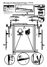
Bei Verwendung von Nicht-HAUTAU-Zentralverschlüssen sind 

die Angaben des jeweiligen Herstellers zu berücksichtigen.

In case of non-HAUTAU central lockings, the specification of the 

corresponding manufacturer has to be considered.

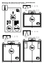
Montage des Zentralverschlusses - Profilquerschnitte  

Mounting of central locking - profile cross-section

D

Summary of Contents for PRIMAT-E kompakt 195

Page 1: ...ten Fenster 1 scherig 10 am scheitrechten Fenster 2 scherig ohne ZV 11 am scheitrechten Fenster 2 scherig mit ZV bei FB 2400 mm 12 am Schrägfenster nur 1 scherig 13 Kopplung von Flügel und Rahmen 14 Montage der Fangschere 15 Montage des Kupplungsteils ZV F nur bei Zentralverschluss 16 Montage des Zentralverschlusses 17 Einstellung des Zentralverschlusses 22 Packaging units 2 Safety instructions 3 ...

Page 2: ...2 Verpackungseinheiten Packaging units ...

Page 3: ...he minimum and maxi mum power ratings and the installation instructions Sicherheitshinweise Sicherheitshinweise die Sie unbedingt beachten müssen werden durch besondere Zeichen hervorgehoben WARNUNG Gefahr für Personen durch elektrischen Strom ACHTUNG Nichtbeachtung führt zur Zerstörung Gefährdung für Material durch falsche Handhabung WARNUNG Gefährdung für Personen durch Gefahren aus dem Geräte b...

Page 4: ...hlenswert Schützen Sie alle Aggregate dauerhaft vor Wasser und Schmutz Leitungsverlegung und elektrischer Anschluss nur durch zugelassene Elektrofirma Netzzuleitungen 230 V AC separat bauseits absichern Netzzuleitungen bis an die Netzklemme ummantelt lassen Bei der Installation DIN und VDE Vorschriften beachten VDE 0100 Errichten von Starkstromanlagen bis 1000 V VDE 0815 Instal lationskabel und le...

Page 5: ...000 105 90 120 135 150 165 180 500 600 700 800 900 1000 1100 1200 1300 1400 1500 1600 1700 400 300 FHs 200 1800 1900 2000 2100 2200 FHs 180 FB 500 FHs 2300 2400 FHs 1 S 190 mm 100 mm 105 90 120 135 150 165 180 1 S Anwendungsbereich Application Für Flügelbreiten FB 2400 siehe Dokument 246375 For sash widhts FB 2400 refer to document 246375 Antrieb ist 32 mm außermittig zum Flügel Drive is 32 mm off...

Page 6: ...0 1900 2500 2600 2700 2800 1400 1500 20 kg m2 25 kg m2 50 kg m2 FH mm FB mm G ZV 2 S M 5 x 18 M 5 x 18 M 5 x 18 Abstand vom Flügelschwerpunkt bis zur Drehachse Distance from center of gravity of sash to pivot I Wert I Value Beispiel Example FB 2 m FH 0 4 m Füllungsgewicht insert element weight 30 kg m Beispiel Example FB 2 m FH 0 4 m Füllungsgewicht insert element weight 40 kg m Beispiel Example F...

Page 7: ...rd jig within scope of delivery Positionen Flügelbock Positions for sash bracket nur bei verdeckter Kabeleinführung siehe Abschnitt Montage des Antriebs in case of concealed cable entry only refer to section Mounting of drive links left Rahmen frame Flügel sash rechts right Flügelgewicht Sash weight Bohrlehren Drilling jigs Informationen bzgl Befestigung Information concerning fastening links left...

Page 8: ... siehe Abschnitt Montage des Antriebs in case of concealed cable entry only refer to section Mounting of drive Anschluss connection 230 V AC Anschluss connection 24 V DC Flügel sash Rahmen frame links left rechts right Pappschablone im Lieferumfang Cardboard jig within scope of delivery Bohrlehren Forts Drilling jigs cont d ...

Page 9: ...schließen close sash Löcher bohren o Abb siehe folgende Seiten drill holes no picture refer to following pages Zentralverschluss in Offenstellung bringen set central locking in position open Platte der Bohrlehre Flügelbock montieren mount plate of jig sash bracket Beispiel scheitrechtes Fenster 1 scherig Flügelbock links rechts entsprechend Example rectangular window single stay sash bracket left ...

Page 10: ...4 V DC in case of concealed cable entry only 24 V DC nur bei verdeckter Kabeleinführung 24 V DC in case of concealed cable entry only 24 V DC AS 0 30 links AS 0 30 rechts nur bei verdeckter Kabeleinführung 230 V AC in case of concealed cable entry only 230 V AC nur bei verdeckter Kabeleinführung 230 V AC in case of concealed cable entry only 230 V AC Montage des Antriebs am scheitrechten Fenster 1...

Page 11: ...le entry only Infolge des symmetrischen Aufbaus kann bei der 2 scherigen Ausführung die elektrische Anschlussseite 24 V 230 V getauscht werden Due to symmetric design of double stay drives the side for electrical connection 24 V 230 V can be changed 24 V DC oder or 230 V AC 230 V AC oder or 24 V DC Für Antriebe ohne Zentralverschluss For drives without central locking Montage des Antriebs am schei...

Page 12: ...erschluss bei FB 2400 mm For drives with central locking in case of FB 2400 mm nur bei verdeckter Kabeleinführung in case of concealed cable entry only nur bei verdeckter Kabeleinführung in case of concealed cable entry only 230 V AC 230 V AC 24 V DC 24 V DC Infolge des symmetrischen Aufbaus kann bei der 2 scherigen Ausführung die elektrische Anschlussseite 24 V 230 V getauscht werden Due to symme...

Page 13: ...0 kg Montage des Antriebs am Schrägfenster nur 1 scherig Mounting of drive at inclined window single stay only nur bei verdeckter Kabeleinführung 24 V DC in case of concealed cable entry only 24 V DC nur bei verdeckter Kabeleinführung 24 V DC in case of concealed cable entry only 24 V DC nur bei verdeckter Kabeleinführung 230 V AC in case of concealed cable entry only 230 V AC nur bei verdeckter K...

Page 14: ...9573 Ausgleichsteil muss lose sein Adjustment part has to be loosened SW 4 Allen key size 4 SW 4 Allen key size 4 Electrical connection PRIMAT E kompakt 195 230 V refer to additional instructions 239570 PRIMAT S kompakt 195 24 V refer to additional instructions 239573 Kopplung von Flügel und Rahmen Coupling of sash and frame Wichtiger Hinweis Wenn der Flügelandruck nicht korrekt eingestellt ist ka...

Page 15: ...0 500 ca 230 350 ca 60 12 12 22 22 22 A9 A13 9 18 15 25 Ø 8 11 5 12 1 11 5 12 1 12 1 12 1 12 1 11 1 Ø 4 0 x 45 Ø 4 8 x 38 BFH x S PS Ø 8 0 45 mm Ø 3 2 3 9 x 4 0 x 4 8 x 38 20 40 60 80 100 100 200 300 400 500 600 700 800 900 1000 1100 1200 2000 BFH mm kg kg 2 1 0 K S P 1 3 0 5 K S P 2 2 1 0 K S P 1 3 0 5 K S P 2 2 1 0 K S P 1 A l u 3 0 5 K S P 2 A l u 12 20 15 16 12 FS 113 FS 114 FS 113 Alu 50 54 8...

Page 16: ...von der Mitte ZV F left sash bracket left from center line ZV F rechts Flügelbock rechts von der Mitte ZV F right sash bracket right from center line zu verwenden To use Montage des Kupplungsteils an der Aufnahme mit weißem Kunststoffteil Mount coupling part at the holder with the white plastic part Montage des Kupplungsteils an der Aufnahme mit weißem Kunststoffteil Mount coupling part at the hol...

Page 17: ...i Verwendung von Nicht HAUTAU Zentralverschlüssen sind die Angaben des jeweiligen Herstellers zu berücksichtigen In case of non HAUTAU central lockings the specification of the corresponding manufacturer has to be considered Montage des Zentralverschlusses Profilquerschnitte Mounting of central locking profile cross section D ...

Page 18: ...1060 FB 720 2400 FH 1101 2400 FFB 680 2360 FFH 1061 2360 L 2 x 1 x FBs 720 2000 FFBs 680 1960 FBs L H H L K K L L K K G G H H L K K G G Ö Ö Ö RC2 Ea Ea Ea 2 x Ia 2 x Ia 2 x Ia D D D D D 2 x G RC2 RC2 Montage des Zentralverschlusses Übersicht Mounting of central locking overview Bei Flügelgrößen außerhalb des angegebenen Anwendungsbereiches siehe Dokument 246375 In case of sash sizes not included w...

Page 19: ... 1 FH 300 500 150 FB 34 3 3 FFB FB FFH FH 3 9 x X Y Y X Z Z Y Z 3 9 x X 3 9 x Montage des Zentralverschlusses Details Mounting of central locking details Ausführung Flügelbock links Ausführung rechts spiegelbildlich version sash bracket left version right mirrored Mitte Flügel center line of sash ...

Page 20: ...1600 40 FB 1201 1600 40 FB 1201 1600 40 FB 1601 2000 292 FB 2001 2400 342 FB 1601 2000 308 FB 2001 2400 358 67 83 FB 1601 2000 308 FB 2001 2400 358 FB 1601 2000 292 FB 2001 2400 342 FB 1601 2000 308 FB 2001 2400 358 67 83 83 67 FB 1601 2000 292 FB 2001 2400 342 RC2 Montage des Zentralverschlusses Schließplatten Mounting of central locking strikers ...

Page 21: ...720 2400 FH 1101 2400 FH 1101 1500 950 FH 1501 1900 1150 FH 1901 2400 1033 FB 1201 1600 40 2 x FS FB 1601 2000 292 FB 2001 2400 342 FB 1601 2000 308 FB 2001 2400 358 67 83 FH 1101 1500 932 FH 1501 1900 1132 FH 1901 2400 1015 RC2 Montage des Zentralverschlusses Schließplatten Mounting of central locking strikers ...

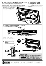
Page 22: ...riebs Zentralverschlusses zur Schließplatte Positioning of drive central locking to striker Einstellen der Überschlaghöhe Adjustment of overrebate height Schließplatte Striker Beispiel Einstellung für 1 scherigen Antrieb 2 scherig entsprechend Example Adjustment for single stay drive double stay accordingly Wichtiger Hinweis Wenn der Flügelandruck durch die Schere nicht korrekt eingestellt ist kan...

Reviews: