


– 21 –
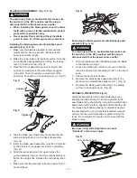
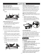
7. Rotate the blade bringing the marked tooth to the
rear and about 1/2 inch above the blade.
8. Carefully slide the combination square to the rear
until the ruler touches the marked tooth.
9. If the ruler touches the marked tooth at the front and
rear position, no adjustment is needed at this time.
If not, perform adjustment procedure described in
next section.
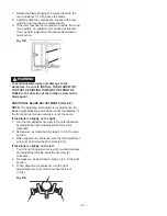
To avoid possible injury and damage to the
workpiece, be sure to INSTALL THE BLADE WITH
THE TEETH POINTING TOWARD THE FRONT OF
TABLE in the direction of the rotation arrow on the
blade guard.
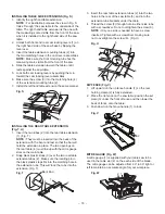
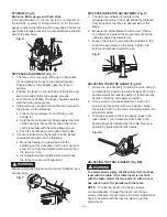
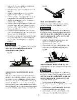
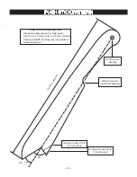
ADDITIONAL BLADE ADJUSTMENTS (FIG. EE)
NOTE:
The adjusting mechanism is located above the
blade height adjusting hand wheel under the tabletop. If
the front and rear measurements are not the same.
If the blade is slightly on the right :
1. Turn the left adjustment screw (2) counterclockwise
and adjust the right side adjustment screw (3)
clockwise.
2. Remeasure, as described in steps 4 to 9 in the prior
section.
3. When alignment is achieved, turn the left adjustment
screw (2) until it touches the pivot rod (4).
If the blade is slightly on the left :
1. Turn the right adjustment screw (3) counterclockwise
and adjust the left side adjustment screw (2)
clockwise.
2. Remeasure, as described in steps 4 to 9 in the prior
section.
3. When alignment is achieved, turn the right
adjustment screw (3) until it touches the pivot
rod (4).
2
1
Fig. DD
Fig. EE
WARNING
!
2
4
3


