


– 18 –
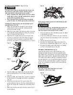
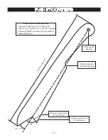
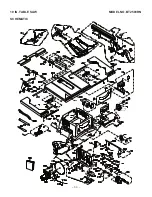
INSTALLING TABLE SIDE EXTENSIONS (Fig. S)
1. Identify the right hand table extension.
NOTE :
For illustration purposes the view in Fig. S
looks “through” the saw table to the underside of the
table. The right hand table extension is the one with
the measuring scale visible from the front of the saw
when it is installed to the right hand side of the saw
table.
2. Unlock both front and rear cam locking levers (1) on
the right hand side of the saw base by flipping the
lever over.
3. Insert the table extension mounting tubes (2) into
the two matching holes in the cam lever assemblies.
NOTE :
Make sure the front mounting tube has the
measuring scale visible from the front of the saw.
4. Slide the table extension toward the table until it
rests against the saw table.
5. Lock both cam locking levers by pushing them in
toward the cam locking lever assemblies.
6. Make sure the screw (3) into the matching hole (4)
of the extension mounting tube (2).
7. Install the left hand table extension the same manner.
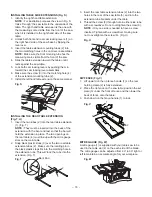
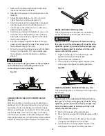
INSTALLING THE REAR TABLE EXTENSION
(Fig. T, U)
1. Insert the two tubes (2) into the rear table extension
(1). (Fig. T)
NOTE :
They must be inserted into the back of the
extension with the bent end last so that the bar will
hold the extension in place. The two openings on
the rear table (4) must line up with the mitre gauge
slots on the main table.
2. Snap black plastic stops (3) over the two rear table
extension tubes (2). Make sure the locating pin in
the black plastic stops fits into the matching hole in
the extension tube. This will ‘lock’ the tube into the
extension. (Fig. T)
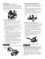
3. Insert the rear table extension tubes (2) into the two
holes in the rear of the saw table (5), and into the
extension tube brackets under the table.
4. Thread the screw (6) through hole in either side tube
with a screwdriver. Do not overtighten the screw (6).
NOTE :
Only one side is needed to have a screw
inserted. Tighten with a screwdriver, making sure
not to overtighten the screw (6). (Fig. U)
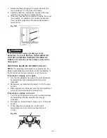
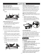
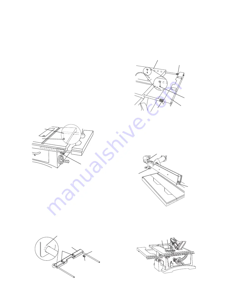
RIP FENCE (Fig. V)
1. Lift upward on the rip fence handle (1) so the rear
holding clamp (2) is fully extended.
2. Place the rip fence on the saw table, position the set
plate (3) under the front of fence and then lower the
back of fence onto the table.
3. Push down on the fence handle (1) to lock.
MITRE GAUGE (Fig. W)
A mitre gauge (1) is supplied with your table saw to be
used in the table slot (2) on the each side of the blade.
The mitre gauge can be adjusted from 90° to 30°
right or
left to maintain an accurate angle for your workpiece.
Fig. S
Fig. T
1
2
Bent End
3
4
3
6
3
1
5
Fig. U
1
2
3
Fig. V
1
2
4
3
Fig. W
1
2


