


– 32 –
10 IN. TABLE SAW MODEL NO. PT2502RN
Any attempt to repair or replace electrical parts on this Table Saw may create a HAZARD unless repair is done by a
qualified service technician. Repair service is available at your nearest Service Centre.
PARTS LIST FOR TABLE SAW SCHEMATIC
WARNING
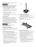
p
!
PARTS LIST
I.D.
Description
Size
QTY I.D.
Description
Size
QTY
2389
WHEEL
1
253S
HANDLE BAR ASS’Y
2
2390
COMPRESSION SPRING
1
255N
HEX. SOCKET HD.CAP SCREWS
M8*1.25-20
4
2552
HANDLE
1
255V
WASHER
T=3mm
1
04Q4
STICKER
1
25JY
SWITCH MOUNTING
1
09JK
WRENCH
1
25MZ
SWITCH BOX
1
0B98
BEVEL GEAR
1
26PT
COMPRESSION SPRING
1
0BAC
SET NUT
1
26VG
WIRE CONNECTOR
1
0BAE
ARBOUR COLLAR
1
26VH
WIRE CONNECTOR
1
0GCM
BEVEL GEAR
1
26YD
LEAD WIRE ASS’Y
1
0HVX
BALL BEARING
2
26YE
LEAD WIRE ASS’Y
1
0J3V
WRENCH HEX.
1
26YF
LEAD WIRE ASS’Y
1
0J4F
FLAT WASHER
φ8*16-2.5
4
28DX
WORM
1
0J4W
FLAT WASHER
φ8.2*18-1.5
4
28DY
BEVEL GEAR
2
0J5A
FLAT WASHER
φ5*16-2
1
28RA
SWITCH BOX COVER
1
0J6T
FLAT WASHER
3/16*3/4-1/16
4
28Z5
ANCHOR BLOCK
2
0J78
FLAT WASHER
1/4*1/2-3/32
3
28Z7
CR. RE. COUNT HD. TAPPING SCREW
M4*16-20
2
0J7U
FLAT WASHER
5/8*1 3/4-11/64
1
2D6H
HEX. SOC. SET SCREW
M6*1.0-6
4
0J8K
FLAT WASHER
1/4*3/4-1/16
1
2FGQ
TILTING SCALE
1
0J94
SPRING WASHER
φ8
4
2GX2
ROCKER SWITCH
1
0JAF
EXTERNAL TOOTH LOCK WASHER
φ5
4
2JHZ
CR. RE. PAN HD. TAPPING SCREW
M5*0.8-12
4
0JB2
WAVE WASHER
WW-12
2
2KVH
CLAMP HANDLE
1
0JCH
SPRING PIN
5-20
5
2LXE
CIRCUIT BREAKER SWITCH ASS’Y
1
0JG4
PARALLEL KEY
2
2NWX
DUST GUARD
1
0JP3
HEX. HD. BOLT
M8*1.25-12
2
2PHA
CR. RE. TRUSS HD. TAPPING SCREW
M5*0.8-12
24
0JPU
HEX. HD. BOLT
M8*1.25-20
4
2PHX
HEX. SOC. TRUSS HD. SCREW
M5*0.8-8
2
0JUL
HEX. SOC. HD. CAP BOLT
M6*1.0-20
6
2QAA
PUSH STICK
1
0JX7
HEX. SOC. SET SCREW
M6*1.0-6
4
2TUY
BLADE GUARD ASS’Y
1
0K05
HEX. SOC. TRUSS HD. SCREW
M8*1.25-20
6
2V3E
BLADE GUARD (RIGHT)
1
0K16
HEX. HD. SCREW AND WASHER
M8*1.25-16
4
2VNQ
BLADE
1
0K19
HEX. HD. SCREW AND WASHER
M10*1.5-25
6
2W7L
CONNECTOR BOX
1
0K24
HEX. SOC. HD. CAP SCREW
M8*1.25-35
4
2W7M
CONNECTOR BOX COVER
1
0K2L
HEX. SOCKET HD. CAP SCREWS
M8*1.25-30
4
2W7Q
BODY SHELL(R)
1
0K4T
CR. RE. TRUSS HD. SCREW
M5*0.8-20
1
2W7R
BODY SHELL(L)
1
0K5B
CR. RE. COUNT HD. SCREW
M6*1.0-12
2
2W7S
BODY SHELL(F)
1
0K5T
CR. RE. COUNT HD. SCREW
M5*0.8-10
4
2W7T
EXTENTION WING
2
0K7D
CR. RE. ROUND WASHER HD. SCREW
M6*1.0-10
4
2W7U
REAR BRACKET
2
0K7F
CR. RE. ROUND WASHER HD. SCREW
M5*0.8-8
8
2W7V
TABLE
1
0K7K
CR. RE. ROUND WASHER HD. SCREW
M6*1.0-12
2
2W89
TABLE SUPPORT ASS’Y
1
0K94
CR. RE. TRUSS HD. TAPPING SCREW
M5*12-16
1
2W8M
BODY
1
0K9P
CR. RE. TRUSS HD. TAPPING SCREW
M6*14-12
1
2W8N
RACK
2
0KA0
CR. RE. PAN HD. TAPPING SCREW
M5*12-20
2
2W8P
CLAMP BAR
1
0KB9
CR. RE. PAN HD. TAPPING SCREW
M5*16-10
7
2W8U
DUST COLLECTOR
1
0KC8
CR. RE. TRUSS HD. TAPPING SCREW
M4*16-16
7
2W8V
SET PLATE
1
0KFG
CR. RE. PAN HD. SCREW
M5*0.8-12
4
2W8W
DUST COLLECTOR JOINT
1
0KK9
SLOTTED PAN HD.SCREW
M6*1.-20
2
2W8Z
ELEVATION SHAFT
1
0KL1
CR. RE. PAN HD. ROUND NECK SCREW
M6*1.0-12
2
2W90
CENTER SHAFT
1
0KMS
HEX. NUT
M6*1.0 T=5
3
2W91
CENTER SHAFT
1
0KMT
HEX. NUT
M8*1.25 T=5
8
2W93
SET BOLT
M8*1.25
6
0KMY
HEX. NUT
M8*1.25 T=6.5
2
2W94
HEIGHT REGULATER BOLT
1
0KN3
HEX. NUT
M16*1.5 T=10
1
2W95
LOCKING ROD
1
0KNV
HEX. NUT
5/8*18UNF T=8
2
2WBV
PULLEY
1
0KQF
CROWN NUT
M8*1.25 T=18
2
2WCH
CUTTER SHAFT
1
0KQP
SQUARE NUT
M8*1.25 T=6.5
8
2WHH
BODY SHELL
1
0KQW
LOCK NUT
M5*0.8 T=5
3
2WJA
SET PLATE
1
0KQX
NUT
M6*1.0 T=6
3
2WJB
SET PLATE
1
0KSC
STRAIN RELIEF
1
2X19
KICK BACK PAWL ASS’Y
1
0KTA
STRAIN RELIEF
5
2X1D
CLAMP BAR
1
0LMK
LOCKING CABLE TIE
1
2X1E
LOCK HANDLE
1
0QGR
COMPRESSION SPRING
1
2X1G
SPECIAL NUT
1
0R25
COLLAR
1
2X1Q
DRIVE BELT,POLY-V BELT
1
0STF
PARRLE RING ASS’Y
1
2X1T
PUSH IN PIN
2
10PM
COPPER BUSH
4
2X1U
SLEEVE-RUBBER
1
145M
SPRING PIN
4.0-40
2
2X5N
LEAD WIRE ASS’Y
1
151G
O-RING ROD
2
2X5P
POWER CABLE
1
20LW
CR. RE. PAN HD. SCREW & WASHER
M5*0.8-16
10
2XHJ
MOTOR ASS’Y
1
216F
SWITCH KEY
1
2XYS
FLAT WASHER
φ8.4*15.5-0.8
1
22VD
PARALLEL PIN
φ=4mm
1
2YQ3
HEX. SOC. HD. CAP BOLT
M8*1.25-75
4
22VF
SLEEVE
1
2YR5
BUSH
2
237F
BEVEL GEAR
1
2ZBE
RIVING KNIFE
1
237G
REINFORCE PLATE
1
2ZDM
MITRE GAUGE ASS’Y
1
237T
SET PLATE
2
2ZDP
RIP FENCE ASS’Y
1
237V
DUST GUARD
1
2ZDV
PLUNGER HOUSING ASS’Y
1
237W
GUIDE BLOCK
1
2ZDX
REAR RAIL (R)
1
237X
SPONGE
2
2ZE1
REAR RAIL (L)
1
237Y
WHEEL
1
2ZGG
HEIGHT LEVER SEAT
1
237Z
SET PLATE
1
2ZTA
CAUTION STICKER
1
238G
LOCATION SEAT
2
2ZTC
LABEL
1
238K
ARM BRACKET
2
2ZTD
SCALE (L)
1
238S
POINTER
1
2ZTE
SCALE (R)
1
238T
ROLLING WHEEL
2
2ZTF
WHEEL CAUTION STICKER
1
239F
RAIL
2
2ZTJ
WHEEL CAUTION STICKER
1
239G
LINK PLATE
1
2ZTK
CAUTION LABEL
1
239H
SIDE COVER (LEFT)
1
2ZUD
COVER
1
239J
SIDE COVER (RIGHT)
1
2ZW5
OPERATOR’S MANUAL
1
23BA
SCREW
M6*1.0
2
30CV
FLAT WASHER
2
23CN
HEX. SOCKET HD.CAP SCREWS
M6*1.0-40
4
31ML
BUSH
2
23KE
HEX. NUT
1
Z06S
TABLE INSERT ASS’Y
1
24ZV
HEX. SOC. SET SCREW
M5*0.8-8
4


