background image

Operator's manual

HA120PX

4000327280

E09.16

USA / GB

Operator's manual

HA120PX

Summary of Contents for HA120PX

Page 1: ...Operator s manual HA120PX 4000327280 E09 16 USA GB Operator s manual HA120PX ...

Page 2: ...2 4000327280 E09 16 USA GB HA120PX ...

Page 3: ...6 3 Safety inquiries 17 4 Incident notification 17 5 Compliance 18 5 1 Productinformation 18 5 1 1 Change of Ownership Notification 18 5 1 2 Owner information update form 19 5 2 Productspecifications 20 B FAMILIARIZATION 1 General safety 21 1 1 Intendeduse 21 1 2 Decalcontent 22 1 3 Symbolsandcolors 23 1 4 Levelofseverity 23 1 5 Symbolslegendanddefinitions 24 2 Models description 25 3 Primary mach...

Page 4: ... Operationfromthegroundcontrolbox 49 1 3 Operationfromtheplatformcontrolbox 51 2 Ground control box 52 2 1 Tostartthemachinefromthegroundcontrolbox 52 2 2 Boomandarmcontrols 53 2 3 Additionalcontrolsfromthegroundcontrolbox 54 3 Platform control box 55 3 1 Tostartandstopthemachine 55 3 2 Driveandsteercontrol 56 3 3 Boomandarmcontrols 57 3 4 Additionalcontrols 58 4 Emergency procedure 59 4 1 Incaseo...

Page 5: ...STEM 77 5 2 1 Description 77 5 2 2 Characteristics 78 5 2 3 Safety precautions 79 5 2 4 Pre operation inspection 80 5 2 5 Operation 82 5 2 6 Specific decals 83 F MAINTENANCE 1 General 85 2 Maintenance Schedule 86 3 Inspection program 87 3 1 Generalprogram 87 3 2 Dailyinspection 88 3 3 Periodicinspection 88 3 4 Reinforcedinspection 88 3 5 Majorinspection 88 4 Repairs and adjustments 89 G OTHER INFO...

Page 6: ...6 Operator s manual ...

Page 7: ...tform We would particularly like to draw your attention to 2 essential points Comply with safety instructions Use the equipment within the specified published performance limits With regard to the designation of our equipment we stress that this is purely for commercial purposes and not to be con fused with the technical specifications Only the specifications in this manual should be used to study...

Page 8: ...o fits loss of motor skills dizziness etc 1 3 TRAINER S RESPONSIBILITY The trainer must be qualified to provide training to operators in accordance with applicable local regulations The training must be given in an obstacle free area until the trainee is considered competent as defined by the training program undertaken 1 4 OPERATOR S RESPONSIBILITY The operator has the obligation to Read and unde...

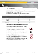
Page 9: ...e defective damaged machine from service Do not climb onto the compartment covers of the machine Do not replace items critical to machine stability with items of different weight or specification Do not replace factory installed tires with tires of different specifications or ply rating Do not alter or disable machine components that in any way affect safety and stability Do not disable the safety...

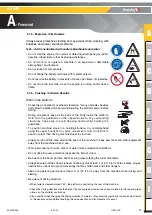
Page 10: ...nts must wear a fall arrest harness with lanyard and energy absorber in accordance with applicable governmental regulations Attach the lanyard to the designated fall arrest anchor provided in the platform The correct use of the harness requires the lanyard to be connected to an anchorage point designated by the decals Refer to this decal located on the platform Hold on securely to the guardrails A...

Page 11: ... limit Do not increase the surface area of the platform exposed to wind This includes adding panels mesh banners Be aware when working with materials with a large surface area This will add to the wind load on the machine Do not raise the platform or drive with platform elevated on an incline exceeding the rated slope for the machine Do not drive the machine on slopes or grades exceeding the speci...

Page 12: ...ion of the slope Always place the boom and the arms in fully retracted and in stowed position Do not travel down slopes in high speed Do not drive fast in narrow or cluttered areas Keep speed under control while making turns or sharp bends WIND The aerial work platform can operate up to a maximum wind speed as indicated in the specifications To identify the local wind speed use the Beaufort scale ...

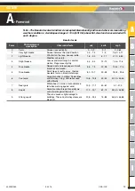
Page 13: ... Slight breeze Leaves and small twigs in constant motion Flags move slightly 3 4 5 4 12 19 7 46 11 8 4 Nice breeze Raised dust and loose papers Small branches are moved 5 5 7 9 20 28 12 43 17 4 5 Nice breeze Small trees in leaf to sway Crested wavelets form on inland waterways 8 0 10 7 29 38 18 02 23 6 6 Cool wind Large branches in motion Power lines and chimneys sing Umbrellas used with difficult...

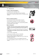
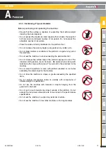
Page 14: ...kV 8 25 500 750 kV 11 35 750 1000 kV 14 45 Do not operate the machine when close to live power lines consider the movement of the machine and the sway of the electric power lines particularly in windy conditions Do not operate the machine during lightning thunderstorms snow ice or any weather condition that could compromise operator safety Do not use the machine as a ground for welding Do not weld...

Page 15: ...ysticks or switches must return to the neutral position before reversing the drive direction and for movement to occur Always wear protective clothing and eye wear when working with batteries and power sources systems N B Acid is neutralized with sodium bicarbonate and water Do not start the engine if you smell or detect liquid propane gas LPG gasoline diesel fuel or other explosive substances Do ...

Page 16: ...achine Limit travel speed to suit the ground surface condition slope incline and people in the vicinity 2 1 7 Uncontrolled movement Hazards Do not use a damaged or malfunctioning machine Be aware of uncontrolled movement and always respect the following Maintain clearance from high voltage lines Maintain clearance from generators radar electromagnetic fields Never expose the batteries or electrica...

Page 17: ...a written response 4 Incident notification Notify HAULOTTE immediately when a HAULOTTE product has been involved in an incident accident leading to personal injury or death or when there is a major property damage HAULOTTE Group EUROPE Product Safety Department Address La Péronnière BP 9 42152 L Horme France Tel 33 0 4 77 29 24 24 Email ProductSafety haulotte com HAULOTTE Group Australia India and...

Page 18: ...nce the bulletin has been addressed make sure that the completed form is submitted to HAULOTTE Do not hesitate to contact HAULOTTE Services should you have any questions relating to the issued bulletin s or with questions on the policy itself 5 1 1 Change of Ownership Notification It is important and necessary to keep HAULOTTE Services updated with current ownership of the machine This way HAULOTT...

Page 19: ... Do not include leased or rented units in this form Current product owner 1 Current product owner 2 Name Name Company Company Address 1 Address 1 Address 2 Address 2 Country Country Phone Phone Date of ownership Date of ownership Signature Signature Date Date Company stamp is mandatory Company stamp is mandatory Tick here if the machine has been permanently removed from service scrapped The manufa...

Page 20: ...n options can modify the machine s operating characteristics and its associated safety If your machine was originally delivered with options fitted replacing a safety component associated with a particular option does not require any particular precaution other than those associated with the installation itself static test Otherwise it is essential to follow the manufacturer s recommendations as s...

Page 21: ...performace specifications tabulation Consult the Beaufort scale Close to power lines Keep a safe distance Outside of the temperature range 20 C 50 C 4 F 122 F In an explosive atmosphere environment During storms In the presence of strong electromagnetic fields N B Usethemachineunder normal climaticconditions Ifyouneedtousethemachineinclimatic conditionslikelytocausedeterioration extreme humidity t...

Page 22: ...azard severity levels CE and AS standards ANSI and CSA standards Decals must be kept in good legible condition Familiarize yourself with the decals and their respective color codes Additional decals can be ordered from HAULOTTE Services Marking Description 1 Hazard symbol 2 Level of severity 3 Avoidance symbol pictorial 4 Avoidance text DANGER 1 2 3 DANGER CRUSH HAZARD Do not stand or walk behind ...

Page 23: ...ibited action Reminder to use good practice or follow pre operation checks Cross reference to another part of the manual Cross reference to another manual Cross reference to repair contact HAULOTTE Services N B Additional technical information Color Title Description Danger Indicates a hazardous situation which if not avoided WILL result in death or serious injury Warning Indicates a hazardous sit...

Page 24: ...ctric arcs Energy supply disconnecting devices Batteries fire emissions etc Risk of operator s falling Tip over due to excessive loading wind load and excessive ground slope Relate and coordinate directional arrows on the chassis with those on the control box Do not put foot in this area Do not put your hand in this area Keep away from product working area Never expose batteries and electrical com...

Page 25: ...A B C D E F G H I 25 4000327280 E09 16 USA GB HA120PX B Familiarization 2 Models description Regulation Models CE AS and EAC standards HA120PX ...

Page 26: ...4000327280 E09 16 USA GB HA120PX B Familiarization 3 Primary machine components 3 1 LAYOUT HA120PX C34 C6 C7 C4 C1 C11 C14 C26 C20 C27 C28 C29 C30 C31 C32 C33 C10 C9 C16 C14 C12 C8 C3 C35 C42 C2 C20 C13 C5 ...

Page 27: ...C5 Platform support incorporating load limiter C28 Tilt Slope sensor C6 Platform C29 Platform rotation cylinder or Platform rotation motor Depending on the machine C7 Platform control box C30 Hydraulic oil tank C8 Input jib compensation cylinder C31 Fuel tank C9 Upper boom C32 Turntable rotation gearbox C10 Slew ring C33 Counterweight C11 Turntable assembly C34 Drive wheels C12 Side cover C35 Docu...

Page 28: ...28 4000327280 E09 16 USA GB HA120PX B Familiarization 3 2 GROUND CONTROL BOX 3 2 1 Layout General view ...

Page 29: ...or placed in transport position 14 Turntable rotation switch Move to the left Counter clockwise CCW rotation Move to the right Clockwise CW rotation 15 E stop button Pulled out Ground control box energized Pushed in De energizes control system 20 Hour meter Total machine running hours 21 Engine revs selector Move to the right Engine speed increases Move to the left Engine idle speed 22 Engine star...

Page 30: ...30 4000327280 E09 16 USA GB HA120PX B Familiarization 3 3 PLATFORM CONTROL BOX 3 3 1 Layout General view ...

Page 31: ...itch Move to the right Counter clockwise CCW rotation Move to the left Clockwise CW rotation 40 Platform leveling switch Move forward Raise platform Move backwards Platform lowers 41 Auxiliary power switch Toggle and hold Back up unit activated Release Back up unit deactivated 42 Engine start up selector Starting the engine 43 Horn button Horn 46 E stop button Pulled out Platform control box energ...

Page 32: ...ability 2WD 40 Maximum rated slope allowed CE AS 5 Maximum load on wheel 2250 6 daN 5059 54 lb Maximum ground pressure of wheel on paved ground 6 9 daN cm 1 44 lb ft Drive speed Folded machine maximum speed High speed Unfolded machine maximum speed Micro speed 0 7 km h 4 5 km h 0 4 m h 2 8 m h Maximum freewheel speed during towed operation 4 5 km h 2 8 m h Outside turning radius 4 90 m 12 ft 4 in ...

Page 33: ...HA120PX 1 m 0 m 0 1 m 2 m 3 m 4 m 5 m 6 m 7 m 8 m 9 m 10 m 11 m 12 m 13 m 1 m 2 m 3 m 4 m 5 m 6 m 7 m 3 ft 1in 0 3ft 1in 6ft 6in 9ft 10in 13 ft 1in 16 ft 4in 19 ft 8in 22 ft 11in 0 3ft 3in 6ft 6in 9ft 10in 13ft 1in 16ft 4in 19ft 8in 22ft 11in 26ft 2in 29ft 6in 32ft 9in 36ft 11in 39ft 4in 42ft 65in m ft in ...

Page 34: ...34 4000327280 E09 16 USA GB HA120PX B Familiarization 5 Decals and markings locations HA120PX CE and AS standards A3 A5 A4 R4 R3 A10 R9 R9 A12 A11 A8 A32 R14 R1 R17 J3 J4 R54 R6 J2 O1 R7 A2 J29 J6 ...

Page 35: ...A B C D E F G H I 35 4000327280 E09 16 USA GB HA120PX B Familiarization A16 A16 A6 R4 R3 J3 R7 J1 A9 R9 R9 R5 A15 R17 A15 A74 R16 J10 R8 R1 A7 R20 R53 R15 A1 R16 ...

Page 36: ...se CE standard 3078145830 In finish CE standard 30781745540 In swedish CE standard 3078145940 In dutch CE standard 3078143470 J1 Yellow Greasing the turntable rotation gear 1 3078143570 J2 Yellow Remove the blocking pin before rotating 1 3078143530 J3 Yellow Do not place your foot on the cover 2 3078143640 J4 Yellow Do not use the machine as a welding earth 2 3078143600 J6 Yellow Verification of t...

Page 37: ...GB HA120PX B Familiarization A74 Other Emergency lowering 1 307P224950 A87 Other Emergency control box 1 For Italy only 307P232500 Not illustrated It is forbidden to use the PVG with a key 4 3078147930 Marking Color Description Quantity HA120PX ...

Page 38: ...38 4000327280 E09 16 USA GB HA120PX B Familiarization Notes ...

Page 39: ...o carry out the work in complete safety and in compliance with this Operator s Manual All managers who are responsible for persons operating the machine must be familiar with the local regulations currently applicable in the country of use and ensure that they are adhered to Before using the machine read the previous chapters in this manual Ensure that you have understood the following points Safe...

Page 40: ...ller doors are opened Comply with permit to work systems where sites have them e g chemical plants Provide a rescue plan for all risks including falls and crush hazards Ensure personnel understand and are appropriately trained in the rescuing procedures Site based personnel trained in operation of functions and in the emergency lowering systems from the ground control box should be present Ensure ...

Page 41: ...ese forms to be completed daily and stored to assist with your maintenance schedule Each action is depicted in the daily inspection sheet using the following symbols Never use a defective or a malfunctioning aerial work platform If any item on the check list is marked No during the inspection machine must be tagged and placed out of service Do not operate the machine until all identified items are...

Page 42: ...on of start stop device Operation of E stop button device Operation of enable switch Operation of horn from platform control box Operation of movement from platform control box Test warning alarm lights and buzzer Overriding indicators turn off after 1 sec No abnormal noise and jerky movements from platform control box Joysticks and movement switches return to neutral Work Platform Floor guardrail...

Page 43: ...Rotation system orientation turret basket and jib No cracks broken weld paint chipped No deterioration and visible damage No screws missing loose parts No foreign body in joints or slides Exterior gear wheel greasing Pin pin stop bearing Presence of the turret pin and its locking device No bent cracked or broken pins pin stops bushes or bearings Pulleys chains and wire rope No cracked or broken ch...

Page 44: ...cables No torn or split wire sheaths No evidence of chemical damage or corrosion on all cables No oxidation or corrosion on terminals Sensors and safety device Activation of Activ Shield Bar Stabilizers operate correctly and lock securely in position Slope limiting device operates properly Axle locking device operate properly Pothole safety device operate properly if equipped Test of load sensing ...

Page 45: ...pecific controls required For the location and description of these controls refer to section B 3 2 and D 2 Ground control box and B 3 3 and D 3 Platform control box 4 1 E STOP BUTTON CHECK Ground control box E stop button Platform control box E stop button 4 2 ACTIVATION OF CONTROLS The enable switch must be active to allow all movements The Enable Switch system depends on the machine configurati...

Page 46: ...allowed load no movement is possible from the 2 control boxes At ground and platform control boxes a buzzer sounds and an indicator light warns the operator To return the machine to normal operation remove weight from the platform until the load is below the maximum allowed load Daily check that the LED s illuminate when the machine is switched on Verify that the Overload system is active Refer to...

Page 47: ...ts 1 Completely retract the boom 2 Lower the boom 3 Lower the arm 4 Lower the jib until it is below horizontal To check the tilt sensor at ground control box Step Action 1 Open the compartment cover C12 Machine components diagram and locate the tilt sensor C28 on the side of the ground control box 2 Pull the E stops 15 46 at ground and platform panels 3 Turn control box selector switch 72 to the r...

Page 48: ...n fully lowered position The only speed allowed when not in stowed position is microspeed This speed is a default speed programed into the machine Daily check that the speed is limited to less than 1 km h 0 6 mph when The boom is raised by more than 10 above horizontal The arm is 30 cm 12 in lifted The jib is above horizontal line 4 8 DRIVE BUZZER For Russia and the Ukraine only Each travel or lif...

Page 49: ...essed in does not turn off the main power supply to the machine An enable switch 228 provided must be activated and maintained to authorize one or more function movements If enable switch 228 is kept engaged without selecting a function movement for more than 8 s enable switch is automatically de activated The release of Enable switch 228 while performing a movement stops all the movements The sto...

Page 50: ...ctivating engine revs selector switch 21 increases engine speed rpm A buzzer beeps in the following conditions When power is switched on Overload if fitted Slope if machine is out of stowed position Hydraulic oil overheating Movements option Driving option Movement option and driving Indicators Cluster All indicators are checked after powering on the machine ...

Page 51: ...ment can occur The release of foot pedal and or control box enable switch while performing a movement stops all the movements The stop of movements is progressive If the foot pedal and or control box enable switch is pressed again quickly within 0 5 s the movement restarts If the foot pedal and or control box enable switch is not pressed again quickly enough within 0 5 s the movement will not rest...

Page 52: ...ical pre heating 1 Low engine oil pressure 2 Engine temperature 3 Battery charge 4 3 The clogged air filter indicator 5 is switched off 4 For machines fitted with Hold down the engine preheating selector 246 for a few seconds indicator 247 lights up 5 Press the starter push button 22 The engine starts The indicator goes out 6 Let the engine heat up To shut down the machine from the ground control ...

Page 53: ... selector 12 upwards to raise the arm Push the arm lift lower selector 12 downwards to lower the arm Boom telescope extend retract Push the boom telescoping switch 9 to the left to extend the boom Push the boom telescoping switch 9 to the right to retract the boom Jib lifting lowering If applicable Push the jib switch 8 upwards to lift the jib Push the jib switch 8 downwards to lower the jib Turnt...

Page 54: ...the beacon selector 24 upwards to switch on the beacon Push the beacon selector 24 downwards to switch off the beacon Engine speed increases Turn the engine speed selector switch 21 to the right to increase speed Turn the engine speed selector switch 21 to the left to idling speed N B Acceleratingtheenginespeedincreasesthespeedofmovementsfromthegroundcontrolbox ...

Page 55: ... 72 to the left to energize platform box The ground box controls are de energized At the platform control box Pull the E stop button 46 if pressed in The power on indicator 31 lights up N B Wait for the engine preheating phase to finish the indicator 1 goes off Press the starter push button 42 The engine starts Let the engine heat up N B Iftheenginedoesnotstart switchofftheignition E stopbuttonpus...

Page 56: ... improve the drive performance Control Action Driving Move the drive joystick 33 forwards to drive the machine forwards Move the drive joystick 33 backwards to drive in reverse Steering Push the steering selector button 33 to the right to steer right Push the steering selector button 33 to the left to steer left Drive speed Position the drive speed selector switch 71 on for high speed driving Posi...

Page 57: ...oping switch 54 forwards to retract the boom Push the boom telescoping switch 54 backwards to extend the boom Lifting lowering of boom Push the boom turntable joystick 49 forwards to raise the boom Pull the boom turntable joystick 49 backwards to lower the boom Lifting lowering of arm Push the arm joystick 50 forwards to raise the arm Push the arm joystick 50 backwards to lower the arm Jib lifting...

Page 58: ... Turntable rotation Move the boom turntable joystick 49 to the left for a clockwise CW rotation Move the boom turntable joystick 49 to the right for a counter clockwise CCW rotation Platform rotation Move the platform rotation selector 38 to the right for a counter clockwise CCW rotation Move the platform rotation selector 38 to the left for a clockwise CW rotation Platform leveling Push the platf...

Page 59: ...nd hold the back up auxiliary power switch 228 at ground box or switch 41 at platform box Retract the boom and lower it by using switches 9 and 10 at ground box or switch 54 and joystick 49 at platform box In an emergency if the operator has to exit the platform while it is elevated the transfer of the operator must respect the following recommendations Exit onto a sturdy and safe structure The oc...

Page 60: ...e ground control box the enable switch 228 must be held activated depressed Procedure Turn the control box selector 72 to the right to energize the ground control box The platform box controls are now de energized Check that the E Stop button 15 at ground is not pressed in To lower the platform hold enable switch 228 downwards and simultaneously push the desired function switch If the E stop butto...

Page 61: ... power and the secondary power unit not functioning do not attempt to activate any function movement using hydraulic manifold unless trained and authorized by HAULOTTE Services All safety functions are no longer active and several hazards may occur Improper use of the equipment will result in death or serious injuries If the operator cannot be lowered by any of the above mentioned methods contact ...

Page 62: ...nd may cause serious injuries and material damage The machine must be completely in the stowed configuration Check the platform is completely empty Lower the boom and drive onto the truck bed Ensure that the jib is raised as necessary to give ground clearance when driving the machine onto the loading ramp Move the platform levelling selector 13 to the right to stow the platform in transport positi...

Page 63: ... E09 16 USA GB HA120PX D Operation instructions 5 2 MACHINE LAYOUT Turret rotation enabled Turret rotation disabled Machine stowing N B Secureturntablewiththeturntablelockingpinbeforetravelinglongdistancesorhaulingmachine on a truck ...

Page 64: ...system lift the jib a few centimetres inches using the ground control box Select low drive speed at the platform control box Start the machine from platform control box To reinstate the system lift the jib a few centimetres inches using the ground control box Warning Upon starting a machine that has been secured and transported the safety system may detect a false overload preventing all movement ...

Page 65: ... braking reverse the steps performed in disengaging the drive hubs 1 Screw the central nut up again to engage the internal gear 2 Engage the driving gear slowly in case of resistance By turning the wheels 3 Screw the central nut up completely when the once the drive gear has commenced to engage In the event of a machine breakdown the machine can be towed a short distance to load it onto a transpor...

Page 66: ... be extended Make sure there is no load in the platform It is recommended that the machine is not stored or immobilized unfolded Ensure all access panels doors and side compartment covers are shut and secured Turn the energizing key selector switch 72 at the ground control box to the center position to shut OFF the power Ensure that the turntable rotation locking pin is removed and stored properly...

Page 67: ... accessories are in good operation and match the technical specifications listed below It is important that the lifting devices are attached only to the designated lifting eyes Each of the chains slings used for lifting the machine must be adjusted to keep the machine level and to minimize the risk of damage to the machine Anchorage point for lifting are identified labeled by the following symbol ...

Page 68: ...tempts refer to the engine maintenance manual N B Initial starting should always be performed from the ground control box 6 1 ENGINE OIL The correct SAE viscosity grade of oil is determined by the minimum ambient temperature during cold engine start up and the maximum ambient temperature during engine operation Generally use the highest viscosity oil that is available to meet the requirement for t...

Page 69: ...rereaches 15 C 59 F It is not advisable to mix oils of different brands or types 6 3 PREHEATING OPERATION When power is switched ON the electric pre heating indicator 1 at the ground control box and or 51 on the platform control box flashes the motor is in automatic pre heating Upon the extinction of this light just seconds at the ground display starting of the machine is possible Environmental co...

Page 70: ...70 4000327280 E09 16 USA GB HA120PX D Operation instructions Notes ...

Page 71: ...A B C D E F G H I 71 4000327280 E09 16 USA GB HA120PX E General Specifications Notes General Specifications ...

Page 72: ...6 USA GB HA120PX E General Specifications 1 Machine dimensions Stowed Transport position Configuration that takes the minimum floor space necessary for storage and or delivery of the machine Access position A J E D B G F ...

Page 73: ... m 18 ft 2 in C Overall height of machine 2 18 m 7 ft 2 in D Wheel base 1 97 m 6 ft 6 in E Ground clearance 30 cm 12 in F X G Platform dimensions 1 5 m x 0 80 m 4 ft 11 in x 2 ft 6 in H Storage length 4 80 m 15 ft 5in J Storage height 2 80 m 9 ft 2 in Component HA120PX Frame assembly mass 1765 kg 3 892 lb Wheel mass of each 120 kg 12 kg 265 lb 26 lb Turret assembly mass 510 kg 1125 lb Counterweigh...

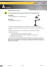
Page 74: ...ub Damage to the tire Cut or hole 3 cm 2 in in the rubber side wall Blister or pronounced lump on the external and lateral wall Damaged wheel stud Damage or wear on the side wall to the extent that the reinforcing wire is visible Consistent wear of the ground contact surface greater than 25 Tires and rims are critical components for the stability of the machine For safety reasons Use only HAULOTTE...

Page 75: ... wheel to be removed Raise the machine using a jack or a hoist Remove the wheel nuts Remove the wheel Install the new wheel Lower the machine to the ground Tighten the wheel nuts to the recommended torque Refer to maintenance and repair manuals N B Ifawheelhasbeenreplaced whileobservingtheaxletrackpatterncheckforcorrectinstallation ...

Page 76: ...on 2 Set the switch selector above the socket power to 1 The green light comes on indicating the on board generator start up 3 Connect the tool to the socket 4 You can change the tool at any time N B Whenusingtheon boardgenerator youcannotmake any machine movements To make a movement you must switch off the on board generator Power off 5 Disconnect the tool from the socket 6 Set the switch selecto...

Page 77: ... provide an alert if this occurs The Activ Shield Bar is enabled when the boom is elevated for operation in confined areas It is not enabled in the transport position when drive turret rotation and raising of the jib to improve visibility are possible Care must be taken during all operations to prevent collision and entrapment against structures It should be noted that this device doesn t release ...

Page 78: ...A120PX E General Specifications 5 2 2 Characteristics Marking Description 1 Activation bar 2 Electrical box 3 RESET push button 4 Green indicator the system is switched on 5 Blue flashing indicator indicates activation bar operates ...

Page 79: ...is never driven any closer than 1 m 3 ft3 in from holes bumps tilts obstructions debris and ground coverings that may hide dangers During operation keep all the parts of the body inside the platform To position the machine close to obstacles it is recommended to use boom movements arm boom etc instead of the drive movements Do not drive fast in narrow or cluttered areas Keep speed under control wh...

Page 80: ...chine functional tests result positive Start the machine from platform control box Switch off pushed in all E Stop buttons Check absence of warning signal Check that the green indicator of the electrical box is switched on Perform the secondary guarding system tests for each movement specified in the table hereinbelow Push the switch bar while operating the movement Check what movement are authori...

Page 81: ...Forward Reverse Left Right Yes No Yes No Yes No Yes No Yes No Yes No Platform control box Forward Reverse Turntable left Turntable right Lifting or telescope extension Telescope descent or retraction Other movement Ground control box All N A N A Authorized Prohibited Authorized if all switches joysticks of the Platform control box are in neutral position or if the Enable switch has been released ...

Page 82: ...sual and audible warnings will alert personal at ground if rescue is necessary To operate safeguard movement from platform control box Joystick and or switch must be reset to neutral position function inactive Enable switch must be activated Operate safeguard movement using joystick or switch to move away from the hazard that triggered the device Press the yellow Reset button 3 to restore normal o...

Page 83: ...83 4000327280 E09 16 USA GB HA120PX E General Specifications 5 2 6 Specific decals Location of the decals Marking Description Quantity Part number 1 Do not lean on the bar 1 4000206690 2 Hand crushing hazard 2 4000244570 ...

Page 84: ...84 4000327280 E09 16 USA GB HA120PX E General Specifications Notes ...

Page 85: ...Use your senses sight smell hearing and touch Frequency Check your machine periodically during your entire workday Make sure to do your inspection the same way every time Complete one of these inspections at the start and end of each shift N B Ifdamageorunauthorizedmodificationsarediscovered themachinemustberemovedfrom service until repairs are made by a qualified service technician It is the owne...

Page 86: ...ding but not limited to severity of operating conditions routine maintenance which should be carried out in accordance with this manual Severity of operating conditions may require a reduction in time between maintenance periods Machines that have been out of service for more than 3 months must undergo a periodic inspection before the machine is put back into service Maintenance must be carried ou...

Page 87: ...e safety register or machine log book controlled and overseen by the company manager This register or machine log book and the list of competent repair persons must be made available to the government work inspector and HAULOTTE Services When Responsible Stakeholder What Before sale Owner or renter Competent technician or qualified technician HAULOTTE Services Periodic inspection Before rent Owner...

Page 88: ...or components Repairs involving the machine s essential components Any accident causing stress to the machine 3 4 REINFORCED INSPECTION The Reinforced inspection is a thorough evaluation of the machine s structural components to ensure proper functionality of the machine This evaluation must occur at a frequency of 5000 hours or every 5 years This inspection is the responsibility of the owner and ...

Page 89: ...AULOTTE Services will not take responsibility for any outcomes resulting from inferior services or repairs performed by other unauthorised personnel HAULOTTE reminds that NO modifications SHALL be carried out without the written permission of HAULOTTE Any unauthorised repairs modifications will void HAULOTTE warranty With the utmost care to ensure enhanced reliability and greater safety of the HAU...

Page 90: ...90 4000327280 E09 16 USA GB HA120PX F Maintenance Notes ...

Page 91: ...ranty is valid for a period of 12 months or up to a maximum of 1000 operating hours for lifting and handling equipment and 2000 operating hours for public works machinery starting from delivery and terminating when the first limit is reached Spare parts are covered by a 6 month warranty 1 2 3 Procedure conditions To benefit from the warranty the owner or rental company must inform the nearest HAUL...

Page 92: ...ed or altered After an unreasonably long delay before reporting a manufacturing problem If the owner or rental company continues to use the machine despite problems If damage is caused by modifications that do not comply with HAULOTTE specifications If lubricants hydraulic oils or fuels that do not comply with HAULOTTE recommendations are used If the machine is incorrectly repaired or used by the ...

Page 93: ...5 6546 6150 FAX 65 6536 3969 E mail haulotteasia haulotte com www haulotte sg HAULOTTE MIDDLE EAST FZE PO BOX 293881 Dubaï Airport Free Zone DUBAÏ United Arab Emirates TEL 971 0 4 299 77 35 FAX 971 0 4 299 60 28 E mail haulottemiddle east haulotte com www haulotte international com HAULOTTE SCANDINAVIA AB Taljegårdsgatan 12 431 53 Mölndal SWEDEN TEL 46 31 744 32 90 FAX 46 31 744 32 99 E mail info ...

Page 94: ...or the engine powered machines destined to the US market Standards ANSI and CSA CALIFORNIA Proposition 65 Warning Diesel engine exhaust and some of its constituents are known to the state of California to cause cancer birth defects and other reproductive harm ...

Reviews:

Related manuals for HA120PX