


10
11
Art. Nr.: 5090033149
Rev.: 01/2020-07-14
Cable entries with integrated patch fl ange -
HSI 150-K(2)-AF/X / HSI 150-1x4-K(2)-AF/X
EN
For the correct installation of cable entries HSI150-K(2)-AF/X
and HSI 150-1x4-K(2)-AF/X with integrated patch fl ange,
the following tools and aids are required in addition to the
usual standard tools:
1 articulated face spanner SLS 6G
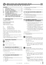
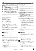
Legend for Fig.: 2
1
Nail holes to affi x the formwork
2
Double wall insert HSI150-K(2)/X
3
Integrated patch fl ange 1x4
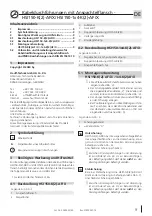
Legend for Fig.: 1
1
Integrated patch fl ange
2
Nail holes
3
Adhesive
4
Lid DT
5
Double wall insert HSI150-K(2)/X
6
Extension pipe
7
Three-ribbed seal
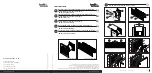
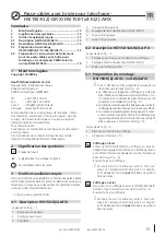
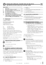
5.1 Installation preparation
HSI 150-K(2)-AF/X / -1x4-K(2)AF/X
• The three arrows on the protective foil have to
be pointing upwards (see Fig.: 3).
• The formwork spacing may not be less than the
set wall thickness “X”. The dimensions are to be
checked prior to installation (see Fig.: 4).
• The integrated patch fl ange has to be lying fl at
on the formwork, covering the entire surface.
• When positioning packages, care must be taken to
ensure that the space between the building edges
of >150 mm is observed (see Fig.: 5).
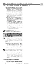
A gap of
≥
5 cm is to be observed between
the three-ribbed seals and the reinforcement.
The tie wire may
not
be attached to the three-
ribbed seals.
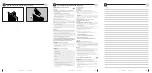
1a
Wood formwork
Nail HSI150-K(2)-AF/X onto the wood formwork using
the nail holes of the integrated patch fl ange provided
and attach with wire to the second reinforcement
layer (see Fig.: 6).
Then close the formwork.
Steel formwork
In the case of steel formwork, HSI150-K(2)-AF/X is to
be attached to the reinforcement by means of wire
(see Fig.: 7).
Then close the formwork.
A gap of
≥
5 cm is to be observed between
the three-ribbed seals and the reinforcement.
The tie wire may
not
be attached to the three-
ribbed seals.
1b
Legend for Fig.: 4
1
Formwork spacing
2
= wall thickness “X”
Contents
1
Publishing notes
Copyright © 2020 by
Hauff-Technik GmbH & Co. KG
Dept.: Technical Editing
Robert-Bosch-Straße 9
89568 Hermaringen, GERMANY
Tel.
+49 7322 1333-0
Fax
+49 7322 1333-999
Internet
www.hauff-technik.de
Reproduction of these assembly instruction – even in
extracts – in the form of reprint, photocopy, on electro-
nic data media or using any other method requires our
written consent.
All rights reserved.
Subject to technical alterations at any time and without
prior announcement.
These assembly instruction is component of the product.
Printed in the Federal Republic of Germany
2
Explanation of symbols
1
Work stages
Reference numerals in drawings
1
►
Effect/result of a work step
3
Required tool and auxiliaries
4.2 Description HSI 150-1x4-K(2)-AF/X
Important points to note when setting in
concrete:
• When concreting and later when compacting the
cable duct trenches, increased care is absolutely
necessary in order to avoid damage due to poor
4.1 Description HSI 150-K(2)-AF/X
1
Publishing notes ...............................................11
2
Explanation of symbols ....................................11
3
Required tool and auxiliaries ...........................11
4.1
Description HSI 150-K(2)-AF/X ..........................11
4.2
Description HSI 150-1x4-K(2)-AF/X ..................11
5.1
Installation preparation
HSI 150-K(2)-AF/X / -1x4-K(2)AF/X ....................11
5.2 Preparation and application notes for cable
entries with integrated patch fl ange and
PMBC coatings according to DIN EN 15814 .....12


