background image


Page 14 
PBG

-9 


11. Prior to restarting the burner system refer to the following sections: Section H – Initial 

Setup, Section I – Ignition, Section J – Operation, Section L – Maintenance. 


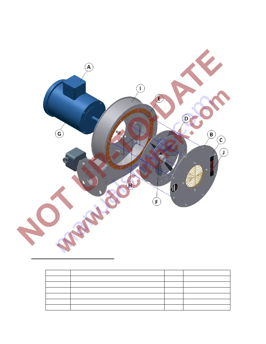
Figure 4. Blower Assembly 


M.   RECOMMENDED SPARE PARTS 


ITEM DESCRIPTION 

QTY. 

PART 

NO. 

Spark Igniter Assembly (If Applicable) 

See Parts List 

Flame Rod Assembly 

See Parts List 

UV Scanner (If Applicable) 

84315205 

4 Opticord 

Adapter 

74960437 

GFK (NFPA Manifold) 

See Parts List 

OMG (If Applicable) 

See Parts List 

Summary of Contents for PBGII

Page 1: ...MANUFACTURING CO P O Box 90 Lebanon PA 17042 0090 717 272 3051 2 12 www hauckburner com Fax 717 273 9882 PBG 9 INSTRUCTIONS These instructions are intended to serve as guidelines covering the installa...

Page 2: ...omer specifications to provide a premier custom engineered product For further information on any components supplied with the package see specific product literature available from Hauck B RECEIVING...

Page 3: ...4 BURNER SPECIFICATIONS HIGH FIRE Body Pressure in w c 6 5 5 2 5 9 5 9 Blower Amp Draw A 0 6 0 7 1 1 1 1 Air Flow scfh 3250 5400 8000 11050 Natural Gas Flow scfh 300 500 750 1000 Flame Length in 12 14...

Page 4: ...Manifold Minimum Supply Pressure in w c 14 14 28 BURNER SPECIFICATIONS HIGH FIRE Body Pressure in w c 5 5 5 5 5 5 Blower Amp Draw A 4 3 4 8 5 5 Air Flow scfh 22250 33000 55000 Natural Gas Flow scfh 2...

Page 5: ...ry air past the firing tube 4 On installations where there is a positive pressure within the combustion chamber the opening in the oven or furnace wall should be at least 1 inch 25mm larger than the b...

Page 6: ...be adhered to Voltage phase and frequency must be compatible with the motor and electrical accessory nameplate ratings All wiring to the burner blower air control motor and control accessories must b...

Page 7: ...ividual burners are within the 20 to 55 in w c 50 to 140 mbar range For accurate burner control the combustion air and gas should be controlled by the components packaged with the burners and not with...

Page 8: ...erationally the actuator must control the valve in the same manner and be able to provide the same ignition point If the air is controlled by VFD the motor will operation between 60Hz at high fire and...

Page 9: ...justment wheel For the GIK clockwise adjustment of the bias screw will increase gas flow while counter clockwise adjustment will decrease gas flow The GIK regulator features a fixed bypass through the...

Page 10: ...iter should be necessary upon initial light off However if ignition problems occur or a new igniter is installed follow the procedure in Figure 3 to replace and adjust the igniter Spark ignition requi...

Page 11: ...shut off valves 3 Check operation of flame safety equipment 4 In addition to leak testing the entire manifold the safety shut off manifold should be leak tested on at least a yearly basis Refer to the...

Page 12: ...eller will cause an imbalance that will result in excessive vibration when the impeller is rotating which can damage motor bearings and other coupled equipment 7 Secure and support the motor G and rem...

Page 13: ...blower housing face plate mounting flange Insert and tighten the eight sheet metal screws B Care should be taken to keep the gasket properly aligned and flat for a proper seal 7 Open the motor wiring...

Page 14: ...ation Section L Maintenance Figure 4 Blower Assembly M RECOMMENDED SPARE PARTS ITEM DESCRIPTION QTY PART NO 1 Spark Igniter Assembly If Applicable 1 See Parts List 2 Flame Rod Assembly 1 See Parts Lis...

Reviews: