Hauck BCS-3000M Instructions Manual Download Page 18


Page 18  

        BCS3000M-9 

APPENDIX F: MATERIAL THERMOCOUPLE INSTALLATION


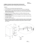
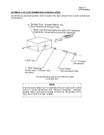
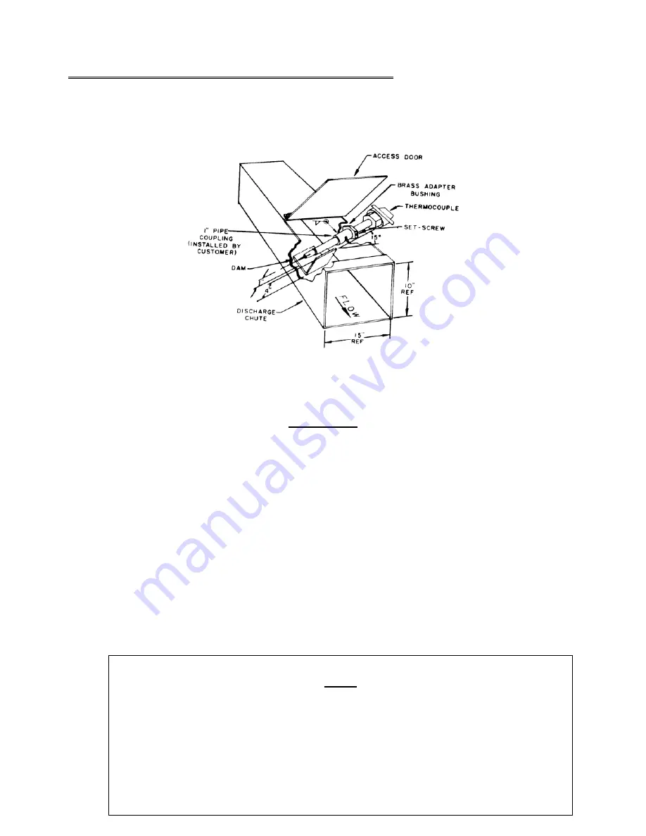
Install a Hauck Rapid Response Material Temperature Thermocouple in the material discharge 
chute to sense the temperature of the material leaving the dryer.  Wire the thermocouple to the 
proper terminals in the panel. 


Drawing showing the placement of the 

thermocouple and "dam" in the dryer discharge chute. 


IMPORTANT 

A small clearance (1" maximum) should be provided under the thermocouple so material 
will not be trapped between the thermocouple and the chute.  Trapped material will cause a 
heat loss path and the thermocouple will give erroneous readings. 

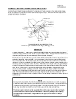
The thermocouple should make good contact with the material but not be subject to severe 
abrasion caused by high velocities.  If the material is moving so fast that it bounces and 
leaves air adjacent to the thermocouple, the temperature it senses will be lower than the 
material.  It may be necessary to place a dam in the chute so that the thermocouple is in a 
relatively slow moving area next to the dam.  The dam must only be wide enough and high 
enough to create a localized area of build-up where the material loses velocity BUT DOES 
NOT STOP FLOWING.  The thermocouple must not be located in a stagnant zone or 
erroneous temperature readings will result.  Because of the large number of variables 
involved, it is impossible to set down any exact size or location of the dam that will always 
work.  Field experimentation will be necessary if good results are to be obtained.  It is 
advisable to tack weld the dam in place so that it can be easily modified if it fails to perform 
satisfactorily. 


NOTE 

During normal operation, the thermocouple should be rotated once a month to expose 
a different area of its surface to the abrasive forces of the material.  This procedure will 
increase the effective life of the thermocouple.  If excessive wear occurs, a protective 
tube may be added to shield the shaft in the region of the high velocity flow. 
 

Thermocouple cables must be separated from AC power and control wiring to 
avoid interference and nuisance shutdowns.  Observe polarity when making 
thermocouple connections.  Regardless of TC type, the red wire is always 
negative.


Summary of Contents for BCS-3000M

Page 1: ...el Adjustment of this equipment and its components by unqualified personnel can result in fire explosion severe personal injury or even death BCS 3000M 9 INSTRUCTIONS These instructions are intended to serve as guidelines covering the installation operation and maintenance of Hauck equipment While every attempt has been made to ensure completeness unforeseen or unspecified applications details and...

Page 2: ... DEC the burner position via the MANUAL switch The left AUTO position enables the Temperature Controller to operate the burner The alarm contact of the High Temp Limit instrument is used to shut down the burner if the preset high temperature limit is exceeded An auxiliary temperature limit is also available as an option Refer to Appendix C for entering the desired alarm setpoints WARNING This equi...

Page 3: ...Assy CY7997 CY7997 CY7997 System Schematic CY7986 CY8078 CY8078 Wiring Diagram CY7995 CY7995 CY7995 External Component Wiring CY8000 CY8114 CY8079 BCI Panel Assembly NA CY7813 CY8034 BCI System Schematic NA CY8108 CY8024 D INSTALLATION 1 Locate the tabletop panel on a firm support in an area that is protected from the weather and free from vibration The drop in version is designed to install in an...

Page 4: ...ee Appendix F for recommended installation 11 Connect the thermocouples to the appropriate terminals in the BCS control panel using thermocouple cable of the same type as the Material and or Stack thermocouples 12 Install the pilot and main flame scanners on the burner and wire them to the appropriate terminals in the burner junction box Reference burner instructions for scanner installation detai...

Page 5: ...issive contacts are closed after the air control valve drives open for purge Eco Star and StarJet conversion burners only F FINAL CHECKOUT 1 Ensure sure that all equipment and components have been installed in accordance with the manufacturer s instructions 2 Verify all wiring and tighten connections 3 Confirm all linkage adjustments and insure that control arms and linkage rods are tight 4 Clean ...

Page 6: ... switches have closed a A message will appear b The START pushbutton will flash indicating that the burner is ready to start 9 Press and hold the START pushbutton to begin the burner ignition sequence a The RM7890A flame relay will be energized b Start Relay R3 will be energized and a ten second trial for ignition will begin c When the message appears the START pushbutton may be released d The ign...

Page 7: ...will drive closed f Purge Relay R4 will be energized H TROUBLESHOOTING PROBLEM POSSIBLE CAUSE CORRECTIVE ACTION No power to instruments or indicator lights L1 fuse blown Check for 120Vac between L1 and L2 Replace 10A fuse L1 Purge limits are not made Check purge limits series 120Vac on terminals 19 24F 24E 24D 24C 24B 24A and 24 Low fire limit switch es are not made Check low fire limit switch es ...

Page 8: ...nal 16 For StarJet EcoStar Check the secondary air interlock contact terminal 14 the primary air interlock terminal 15 the primary air or compressed air pressure switch terminal 15A and the secondary air pressure switch terminal 16 Low gas pressure fault Check the low gas pressure limit switch 120Vac on terminal 16A High gas pressure fault Check the high gas pressure limit switch 120Vac on termina...

Page 9: ...ppears replace pilot scanner If signal remains replace main flame scanner Flame relay ALARM led indicator comes on and will not reset Improper grounding or voltage polarity Flame relay failure Verify neutral L2 of 120Vac supply is grounded Verify that control panel is grounded Replace flame relay amplifier and or relay module indication but fuel control motor will not drive Fuse 5 blown Pilot time...

Page 10: ...nable the burner control motor to be driven by the Honeywell Temperature Controller without having to fire the burner 3 Turn the panel power on Enter the calibration mode on the Temperature Controller by pressing the SETUP key until the display reads CALIB POSITION 4 Press the FUNCTION key to display DISABLE POS PROP then press the key to change the upper display DO AUTO 5 Press FUNCTION to begin ...

Page 11: ...eld adjustments other then as noted in this instruction sheet PLEASE CONTACT THE HAUCK SERVICE DEPARTMENT I OPERATOR INTERFACE Figure 1 shows the front face of the UDC3200 instrument This section describes the function of the various displays and keys Examples are given for changing the controller setpoint and operating the burner in MANUAL Detailed information is given in the vendor literature su...

Page 12: ...digit one place to the left To decrease the set point value reverse the above procedure EXAMPLE 2 ADJUSTING THE BURNER FIRING RATE IN THE MANUAL MODE Press the AUTO MANUAL key to place the Controller in the Manual Mode The MAN indicator will come on and the lower display will automatically change to show OUT Press and hold the key to increase Output value To make changes more quickly press the key...

Page 13: ...UNE FUZZY DISABLE __________ ACCUTUNE DISABLE __________ ALGORITHM CONT ALG PID A __________ TIMER DISABLE __________ IN ALG 1 NONE __________ OUT ALG OUT ALG POSITN __________ MOTOR TI 40 __________ INPUT 1 IN 1 TYPE J TC L __________ IN 1 HIGH 550 0 F __________ IN 1 LOW 20 00F __________ RATIO 1 1 000 __________ BIAS IN 1 0 0 __________ FILTER 1 1 __________ BURNOUT 1 UP __________ INPUT 2 IN 2...

Page 14: ... AUTO OUT 0 0 __________ PB OR GAIN PB PCT __________ MIN OR RPM RPM __________ COM COM ADDR 3 __________ COMSTATE DISABLE __________ IRENABLE ENABLE __________ BAUD 19200 __________ TX DELAY 1 __________ ALARMS A1S1 TYPE NONE __________ A1S2 TYPE NONE __________ A2S1 TYPE NONE __________ A2S2 TYPE NONE __________ ALARM HYST 0 1 __________ BLOCK DISABLE __________ DIAGNOST DISABLE __________ A1S1 ...

Page 15: ... display reads SETP then press SETUP again to display the current setpoint Use the or keys to change the setpoint Hold SETUP and press the key then release the SETUP key and press the key until the upper display again reads OPTR then press SETUP to return to the operating normal display CONFIGURATION RECORD SHEET SLCT CONF ULOC 20 LOWER DISPLAY FACTORY FINAL FUNCTION CONFIGURATION SETTING INPT J F...

Page 16: ...o the duct and hold in place 4 Using the second half of the flange tighten the 1 4 20 bolts to hold the pitot in place 5 WARNING Do not fasten both halves of the flange One side is left unbolted for removal and cleaning of Pitot tube 6 For other applications weld the four duct mounting nuts to the inside of the ductwork using the flange as a pattern 7 Use silicone caulk as a gasket 8 Remote mount ...

Page 17: ...st duct to sense exhaust gas temperatures Drawing showing placement of thermocouple in exhaust duct NOTE Thermocouple cables must be separated from AC power and control wiring to avoid interference and nuisance shutdowns Observe polarity when making thermocouple connections Regardless of TC type the red wire is always negative ...

Page 18: ... slow moving area next to the dam The dam must only be wide enough and high enough to create a localized area of build up where the material loses velocity BUT DOES NOT STOP FLOWING The thermocouple must not be located in a stagnant zone or erroneous temperature readings will result Because of the large number of variables involved it is impossible to set down any exact size or location of the dam...

Page 19: ...00 17292 2 Relay 3PDT P B KUP 14A35 or equal 61961 1 Purge timer ATC 407B 100 F3K 40744 1 Timer 10 second solid state Omnetics MMS115A19 1 2B 40747 1 Timer 3 second solid state Omnetics MMS115A1Z3B 55167 5 Fuse 7A 1 4 x 1 1 4 Littlefuse type 313007 48044 5 Fuse 10A 1 4 x 1 1 4 Littlefuse 312010 43508 or 43508R2037 1 Material thermocouple Hauck TC100A J or Material thermocouple Hauck TC100A K 43868...

Page 20: ...Page 20 BCS3000M 9 This page left intentionally blank HAUCK MANUFACTURING CO P O Box 90 Lebanon PA 17042 0090 717 272 3051 www hauckburner com Fax 717 273 9882 ...

Reviews: