background image

HFS6801

+

 Installation and Operation Manual

17

Chapter 2: Installation


2. Remove the module from the 6800

+

 frame.

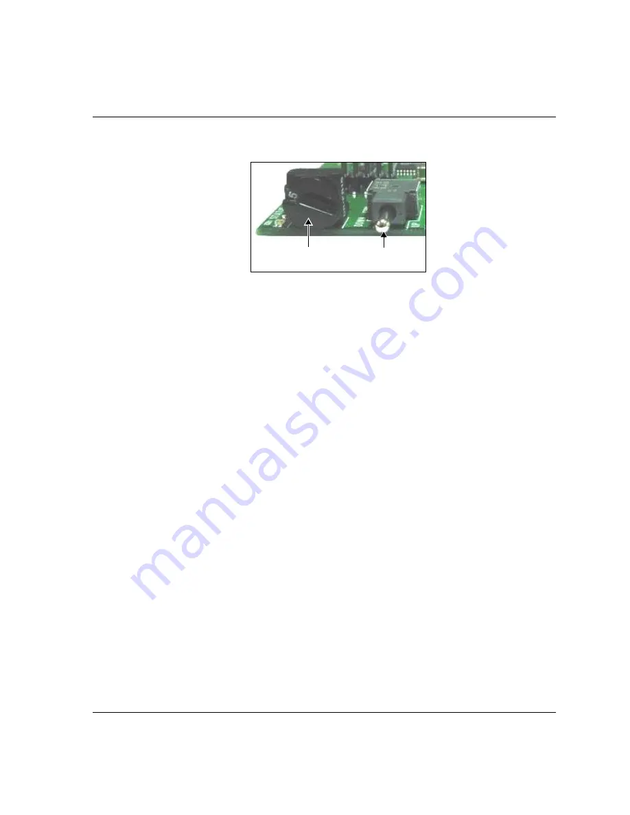
Figure 2-3. Buttons on a Typical Card Edge

3. Set the Hex switch to 

F

4. While pressing the Navigation toggle switch down, reinsert the 

module into the frame and then release the Navigation toggle 
switch.

5. Perform a Discovery operation to discover the module, as described 

in 

“Discovering a DAV6800

+

 Module” on page 30

Information about discovering modules can also be found in 
your CCS software application manual or online help. (If you 
cannot discover the device, see 

“Manually Adding a Device to 

the Discovery or Network Folder” on page 21

.)

Mode select rotary 

(hex) switch

Navigation toggle 

switch

Summary of Contents for HFS6801+

Page 1: ......

Page 2: ......

Page 3: ...Edition B April 2007 HFS6801 HD SD TV Video Frame Synchronizer Installation and Operation Manual...

Page 4: ...cally added to the information herein these changes will be incorporated into new editions of the publication Harris Corporation may make improvements and or changes in the product s and or the progra...

Page 5: ...on ix Unpacking a Product ix Product Servicing ix Returning a Product ix Restriction on Hazardous Substances RoHS Compliance x Waste from Electrical and Electronic Equipment WEEE Compliance xi Safety...

Page 6: ...talling and Removing Modules 14 Making Connections 15 Upgrading Module Firmware 16 Upgrading the Firmware 16 Correcting a Failed Upgrading Procedure 20 Chapter 3 Operation Overview 23 Operating Notes...

Page 7: ...t Lite Fails to Communicate with Installed Modules 47 Pilot Lite Does Not Find All Modules in Frame 48 Pilot Lite or CCS Software Application Not Responding 49 Pilot Lite Cannot Control a Module Showi...

Page 8: ...vi HFS6801 Installation and Operation Manual Contents...

Page 9: ...D TV Video Frame Synchronizers Audience This manual is written for engineers technicians and operators responsible for the installation setup and or operation of HFS6801 HD SD TV Video Frame Synchroni...

Page 10: ...tons check boxes list boxes combo boxes menus submenus windows lists and selection names Italics Indicates email addresses the names of books or publications and the first instances of new terms and s...

Page 11: ...ield servicing All hardware upgrades modifications or repairs require you to return the modules to the Customer Service center Returning a Product In the unlikely event that your product fails to oper...

Page 12: ...tive which took effect on July 1 2006 refers to the following hazardous substances Lead Pb Mercury Hg Cadmium Cd Hexavalent Chromium Cr V1 Polybrominated Biphenyls PBB Polybrominated Diphenyl Ethers P...

Page 13: ...ere required to recycle electrical and electronic equipment at end of its useful life and may not dispose of the equipment in landfills or by using other unapproved methods Some EU member states may h...

Page 14: ...oduct relies on forced air cooling it is recommended that all obstructions to the air flow be removed prior to mounting the frame in the rack If this product has a provision for external earth groundi...

Page 15: ...to a local station clock and allowing the clean processing of all synchronized signals The module provides video frame synchronization and delay for HD and SD TV signals and picture control through a...

Page 16: ...tracking audio processing The HFS6801 module s reference input located on the back connector and the 6800 frame s genlock connector both provide a reference signal This module can be controlled local...

Page 17: ...24 25 29 97 30 Hz 720p progressive 50 59 94 60 Hz Standard definition 525 625 Auto detect or user forced input video standard 10 bit video processing Digital equalization supports Belden 8281 and new...

Page 18: ...jumpers The number of Control and Monitoring LEDs on 6800 modules varies Figure 1 1 Typical 6800 Module Table 1 1 on page 5 briefly describes generic 6800 LEDs switches and jumpers See Chapter 3 Oper...

Page 19: ...parameters Up Moves up through the parameters Control LEDs Various lighting combinations of these Control LEDs sometimes referred to as Bank Select LEDs indicate the currently selected bank See Table...

Page 20: ...connector used by the HFS6801 module when installed in an FR6802 XF frame Figure 1 2 HFS6801 Back Connector SDI IN AUX IN GENLOCK 2 4 5 6 1 3 SDI OUT SDI OUT RCLK DATA I O SDI video in Auxiliary input...

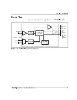
Page 21: ...Flow Figure 1 3 shows the basic signal flow of the HFS6801 modules Figure 1 3 HFS6801 Signal Flow Diagram SDI input EQ reclock CCS control monitor port Genlock Re clocked SDI outputs Four SDI outputs...

Page 22: ...8 HFS6801 Installation and Operation Manual Chapter 1 Introduction...

Page 23: ...Upgrading Module Firmware on page 16 See the FR6802 Frame Installation and Operation Manual for information about installing and operating an FR6802 XF frame and its components Caution Before install...

Page 24: ...the maximum allowable power ratings for 6800 frames Note the given maximums before installing any 6800 modules in your frame Table 2 1 Maximum Power Ratings for 6800 Frames 6800 Frame Type Max Frame P...

Page 25: ...packaging material Note Contact your Customer Service representative if parts are missing or damaged Retain the original packaging materials for possible re use See Unpacking Shipping Information on p...

Page 26: ...Jumper Note You need to configure modules for local or remote operation prior to power up To change the configuration first remove power from the module reset the jumper and then reapply power Follow...

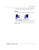
Page 27: ...ins 2 and 3 to set the module for Local control See Figure 2 2 Note The white triangle near the jumper pins on the module indicates pin 1 Figure 2 2 REM LOC Settings for Remote and Local Control See T...

Page 28: ...nstructions Installing and Removing Modules These modules require no specialized installation or removal procedures However if installing both front and rear modules ensure that the back module is ins...

Page 29: ...e that the data I O output provides reference signals for 6800 audio tracking modules It can drive up to four chained audio modules over coaxial cable up to 985 ft 300 m long If you wish to connect to...

Page 30: ...e of such situations as network interruptions power failures etc the module may not respond to controls and will appear to be non functional In that event follow the procedures described in Correcting...

Page 31: ...into the frame and then release the Navigation toggle switch 5 Perform a Discovery operation to discover the module as described in Discovering a DAV6800 Module on page 30 Information about discoverin...

Page 32: ...l items in a frame have the same IP address The selected devices appear in the table under Device Name These devices will receive the same upgrade package 9 Before proceeding with the firmware upgrade...

Page 33: ...s tab to view the status of the transfers Closing the Software Upgrade window does not effect any of the transfer processes that may be running in the background If you try to log off or exit the CCS...

Page 34: ...ckage from our Web site or from your CD ROM do so now Putting the Module in Boot Loader Mode Follow these steps to put your the module in Boot Loader mode 1 Remove the affected module from the 6800 fr...

Page 35: ...and then drag or copy and paste the module s device icon from the Catalog folder into the Network or Discovery folder 2 Right click the device icon and then select Properties 3 On the Device tab of th...

Page 36: ...tion 4 In the third field enter 1 0 slotnumber where for example 1 0 5 would refer to the module in slot 5 of the frame number 0 5 Close the window 6 You can now continue your firmware upgrade as desc...

Page 37: ...product remotely Pilot Lite User Manual for serial control interface CCS Pilot CoPilot Navigator or RCP CCS 1U Remote Control Panel manual for Ethernet control interface The following topics are disc...

Page 38: ...quires up to 20 seconds to save the latest change After 20 seconds the new settings are saved and will be restored if the module loses power and must be restarted When you set the Factory Recall param...

Page 39: ...tdSet is set to Auto and SdiStdFdbk is SD 525 or SD 625 Note The parameter Hue is only available in SD 525 mode Table 3 1 Parameter Availability Based on Operating Mode Condition Enabled Parameters Di...

Page 40: ...the two control LEDs next to the navigation toggle switch to see which bank is currently selected See Table 3 3 on page 29 to view the various banks hex switch positions and corresponding parameter op...

Page 41: ...on switch to the bank number 0 Use the control LEDs to verify which bank you have selected or use an available 6800 software control option serial local or Ethernet remote to aid in confirming your ba...

Page 42: ...nce achieved when you move the Navigation Toggle switch up The On Off combinations of the control LEDs on the card edge indicate the active bank number See Changing Parameter Settings on page 26 for m...

Page 43: ...P 50 0 2 Y CRC Err Cnt Clear Clears the luminance CRC error counter On Off 0 3 C CRC Err Cnt Clear Clears the chrominance CRC error counter On Off 0 4 EDH Error Cnt Clear Clears EDH error counter On O...

Page 44: ...1 s 0 0 to 63 519 s 0 0 to 63 963 s see cross functional parameter changes table 0 B Delay Range Adjusts the amount of frame delay 0 to 7 frm 0 to 1 frm 0 to 15 frm see Cross Functional Parameter Chan...

Page 45: ...ff On 1 6 White Clip Level Sets the white clipping level 636 87 to 763 13 mV 700 0 1 7 White Clip Controls the activation of White Clip Off On 1 8 Hue Adjusts the hue of the incoming digital video sig...

Page 46: ...80I 30 SD 525 SD 625 720P 50 1080PsF 23 98 1080PsF 24 720P 29 97 720P 30 720P 25 720P 23 98 720P 24 1080PsF 29 97 1080PsF 30 RO SDI IP Video Present Reports the presence of the HD SDI input video sign...

Page 47: ...video signal from the external reference source No Yes RO GL Video Locked Reports the locked status of the external reference signal No Yes RO Genlock Std Feedback Reports the detected Genlock standar...

Page 48: ...y Input Standard and Frame Rate Parameter Name SDI Input Video Standard and Frame Rate SD 525 SD 625 1080I 30 29 97 and 25 1080P 30 29 97 25 24 and 23 98 720P 60 59 94 and 50 Vertical Phase 0 to 524 l...

Page 49: ...describes each LED in more detail Figure 3 1 Location of Card Edge LEDs The 9 monitoring LEDs on the card edge of HFS6801 modules are identified in Figure 3 1 left to right Table 3 5 Monitoring LEDs...

Page 50: ...resent 525 Indicates if a 525 video source is present GREEN 525 video present OFF 525 video not present 625 Indicates if a 625 video source is present GREEN 625 video present OFF 625 video not present...

Page 51: ...and Table 3 6 below for a definition of the LED colors Note If the LED is flashing red please contact your Customer Service representative Table 3 6 Module Status LED Descriptions LED Color Sequence...

Page 52: ...applications The appropriate software control user manual or online help for more information Note The RefPresAlarm RefLockedAlarm and RefStdMismatch alarms are disabled when the Frame Sync Mode param...

Page 53: ...rview The following specification tables appear in this chapter SDI Video Input on page 40 SDI Video Output on page 41 Propagation Delay on page 42 Power Consumption on page 43 Operating Temperature o...

Page 54: ...D SDI and 259M C SD SDI Connector BNC IEC169 8 Impedance 75 Return loss 18 dB typical from 5 MHz to 1485 MHz HD SDI mode 18 dB typical to 270 MHz SD SDI mode Equalization Adaptive cable equalization f...

Page 55: ...loss 18 dB typical from 5 MHz to 1485 MHz HD SDI mode 18 dB typical to 270 MHz SD SDI mode Signal level 800 mV 10 D C offset 0 0 V pk to pk 0 5 V Rise fall time 270 ps within 100 ps of each other HD...

Page 56: ...nnector BNC per IEC 169 8 Impedance 75 Return loss 35 dB to 30 MHz Item Specification Processed video minimum delay setting SD 525 5 07 s SD 625 5 07 s 1080i 29 97 Hz 8 50 s 1080i 30 Hz 8 50 s 1080p 2...

Page 57: ...4 Specifications Power Consumption The total power consumption for the HFS6801 is approximately 7 W from the positive rail and 0 3 W from the negative rail Operating Temperature The operating tempera...

Page 58: ...44 HFS6801 Installation and Operation Manual Chapter 4 Specifications...

Page 59: ...Troubleshooting Tips Overview Find the following troubleshooting information in this appendix General Troubleshooting Steps on page 46 Software Communication and Control Issues on page 47 Hardware Co...

Page 60: ...in the product specific manual that accompanies every module in the FR6802 Frame Installation and Operation Manual and in the 6800 Safety Instructions and Standards Manual Product documentation includ...

Page 61: ...dule slot has not been specified Pilot Lite is not communicating with the appropriate slot See your FR6802 Frame Installation and Operation Manual for more information on slot identification COM port...

Page 62: ...ve the back module c View the 20 pin spring connector at the bottom of the back module See Figure A 1 Figure A 1 Back Module to Front Module Connector This connector should not have any bent or presse...

Page 63: ...s can be installed but only one can be opened at a time Pilot Lite Cannot Control a Module Showing in the Control Window Consider these questions Did you physically set the jumper for local control If...

Page 64: ...an ICE6800 module in an FR6802 frame in order to communicate remotely via Ethernet Alarm Query Fails When a Device Reboots When you reboot a device connected to your PC the alarm traffic hitting the...

Page 65: ...mes have three or more minutes to recover from the power failure before you exit the application and restart the PC Module Does Not Seem to Work Although the following troubleshooting tips may seem ob...

Page 66: ...52 HFS6801 Installation and Operation Manual Appendix A Communication and Control Troubleshooting Tips...

Page 67: ...RC error counter 29 clipping level 31 Communication failure frame 51 Connections internal 14 Control problems 49 CoPilot 49 Correcting failed upgrades 20 D DC offset 41 default parameter settings reca...

Page 68: ...ce CRC error counter 29 M making connections 15 Maximum allowable power ratings 10 Module not found 48 Module software upgrading 16 22 module status LEDs 37 monitoring LEDs 35 N Navigation Properties...

Page 69: ...el 41 Software upgrading 16 22 software version 27 specifications 39 43 standard video 41 Standards RoHS compliance x WEEE compliance xi Status not ready 49 Support documents viii T test signal genera...

Page 70: ...56 HFS6801 Installation and Operation Manual Index...

Page 71: ......

Page 72: ...tal Way Mason OH USA 45040 Tel 1 513 459 3400 www broadcast harris com Copyright 2006 Harris Corporation Harris and Leitch are registered trademarks of Harris Corporation Trademarks and tradenames are...

Reviews: