background image

Chapter 2 Introduction

Video Encoding Features

 © 2012 Harmonic Inc.

12

Electra 1000, Version 3.0, Rev M

2.3 

Video Encoding Features 

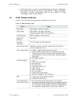
Table 2-2 describes video encoding features supported by the encoder.

a.

HE AAC, also known as aacPlus, was developed by Dolby Germany. Dolby Digital, 

Dolby Digital Plus, aacPlus, and Dolby E are trademarks of Dolby Laboratories. 
Trademarks of Coding Technologies GmbH are the property of Coding 
Technologies GmbH. All rights reserved.

Table 2-2: Video Encoding Features  

Feature

Support

Input format

Serial digital or analog composite

Video format

Serial digital:  525-lines or 625-lines
Analog composite: NTSC, PAL, and PAL-M

Encoding mode

MPEG-2 MP@ML 4:2:0 encoding

Repeat field 
detection

Supported

Horizontal 
resolutions

720, 704, 640, 544, 528, 480, 352

Advanced encoding

Alternate scan mode, zig-zag mode, flexible GOP structure, 


4:3 and 16:9 aspect ratio

Video preprocessing

ENRGY™ Integrated Noise Reduction System

Horizontal filter, border processing, nonlinear spatial filter, 
impulse noise reduction, motion compensated temporal low 
pass filter (MCTF), luma and chroma filter, and edge-adaptive 
texture filter

PSIP tables spooling

Closed captioning

Line 21

ATSC Line 21 CEA-608

ITU-R BO.1294

DVS-157 (GI CC)

SCTE 20 (True DVS-157)

SAUD (SA CC)

DMV1 (Tandberg CC)

DVS-157+SAUD

Extend Data Services (XDS)

(525-line VBI) 608 to 708 conversion

VBR

Support for variable bit rate encoding

Capped VBR (open loop)

Accommodates poor 
quality video sources

To compensate for poor analog sources, the encoder 
preprocesses the area around the line sync, slightly expanding 
both the front and back porches to enhance timing recovery. 
As a result, the encoder slightly reduces the line length. When 
this capability is engaged, all alarm reporting is disabled.

Summary of Contents for Electra 1000

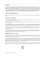
Page 1: ...Electra 1000 Multichannel Encoder Installation Guide Rev M Manual Part No MAN ELECTRA1000 3 0 ...

Page 2: ...his equipment in a residential area is likely to cause harmful interference If this occurs the user will be required to correct the interference at his or her own expense This device complies with Part 1 5 of the FCC rules Operation is subject to the following two conditions 1 this device may not cause harmful interference and 2 this device must accept any interference received including interfere...

Page 3: ...ated or stored as per the conditions specified in the product manual O 表示在该部件的所有均质材料中 此类有毒有害物质的含量均小于 SJ T11363 2006 标准所规定的限量 O Indicates the content of the toxic and hazardous substances at the homogeneous material level of the parts is below the limit defined in SJ T1 1 363 2006 standard X 表示至少在该部件的某一均质材料中 此类有毒有害物质的含量超出 SJ T11363 2006 标准规定的限量 X Indicates that the content of the toxic and hazardou...

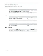
Page 4: ...apan Australia and New Zealand Standards Agency Approval EMI FCC Part 1 5 Subpart B ICES 003 Issue 2 Class A FCC Safety UL 60950 CSA 60950 cTUV us Mark Standards Agency Approval EMI EMC EN55022 Class A EN55024 CE Safety EN 60950 TUV GS Mark CE Standards Agency Approval EMI VCCI V 3 2000 04 VCCI Standards Agency Approval EMI AS NZS 3548 1995 A1 1997 A2 1997 N A ...

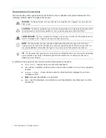
Page 5: ...al information that you will benefit from heeding It may be used to call attention to an especially important piece of information you need or it may provide additional information that applies in only some carefully delineated circumstances TIP The Tip symbol calls your attention to parenthetical information that is not necessary for performing a given procedure but which if followed might make t...

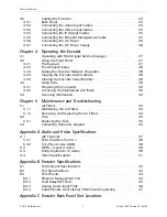
Page 6: ...ront Bezel 15 2 9 2 Local Control Panel 15 2 9 3 LEDs 15 2 9 4 Modes of Operation 16 2 10 Back Panel 16 2 10 1 AC Power and Fuse 17 2 10 2 DC Power and Fuse 17 2 10 3 Audio Input Ports 17 2 10 4 Video Input Ports 18 2 10 5 IP Output Port 18 2 10 6 Ethernet Management Port 18 2 10 7 Fault Relay Port 18 2 10 8 Serial Data Port 19 2 11 Back Panel LEDs 19 2 11 1 Main Board LEDs 19 2 11 2 Video Lock LE...

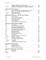
Page 7: ...ing SAG 29 4 3 1 Preparing the Computer 30 4 3 2 Accessing the Standalone GUI SAG 30 4 4 Licensing Information 32 Chapter 5 Maintenance and Troubleshooting 5 1 Air Filters 33 5 1 1 Maintaining the Air Filters 33 5 1 2 Removing and Replacing the Air Filters 34 5 2 Fuse 35 5 2 1 Replacing the Fuse 35 5 3 Contacting Harmonic Support 35 Appendix A Audio and Video Specifications A 1 AIC Features 37 5 3...

Page 8: ...E 6 Assembling the DC Input Power Cable 54 Appendix F FLEX Decoding Module F 1 Introduction 55 F 2 Video Decoding Specifications 55 F 3 Audio Passthrough Specifications 56 F 4 Audio Decode Specifications 57 F 4 1 Decoding Resource Considerations 57 F 5 Ancillary Data Specifications 59 F 6 Input Specifications 59 F 7 Output Specifications 60 F 8 Environmental and Physical 61 F 9 Module Slots 61 F 1...

Page 9: ... specifications for AIC and video encoding Appendix B Encoder Specifications describes specifications and physical characteristics of the back panel ports and port pinouts environment specifications and input and output specifications Appendix C Encoder Back Panel Slot Locations shows the numbering of the back panel slots NMX uses the slot number to differentiate between cards of the same type wit...

Page 10: ...iguration of the Electra 1000 platform ports services and PSI as well as alarm management You configure a few initial network settings from the front panel of the encoder The encoder operates within an IP environment therefore encoders and multiplexers do not need to be in the same physical location Harmonic recommends discussing your planned network architecture with a Harmonic representative bef...

Page 11: ... 2 0 Only port 1 is capable of Multichannel 3 2 on the AHC 561 or AHC RAC Fixed Audio Gain AIC card Low Delay Audio Encoding Audio description for audio coding AIC RAC and on board audio Dolby Digital Plus passthrough IP output MPEG 2 Transport Stream TS over UDP One 10 100 1000 Base T port with second redundant channel connector Dual mode IP output or manual channel switch for redundancy Hot warm...

Page 12: ...dvanced encoding Alternate scan mode zig zag mode flexible GOP structure 4 3 and 16 9 aspect ratio Video preprocessing ENRGY Integrated Noise Reduction System Horizontal filter border processing nonlinear spatial filter impulse noise reduction motion compensated temporal low pass filter MCTF luma and chroma filter and edge adaptive texture filter PSIP tables spooling Closed captioning Line 21 ATSC...

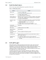
Page 13: ...ectra 1000 encoder must be sent to the same ProStream 1000 MPTS multiple STC clocks per chassis is also supported Table 2 3 Audio Encoding Features Feature Support Stereo pairs Up to 10 stereo pairs Two stereo pairs per audio input card Input format Digital AES3 or S PDIF Analog balanced or unbalanced Analog reference level specification Reference levels in the range 10 dBu to 4 dBu may be specifi...

Page 14: ...with AHC RAC audio adapters mounted can support one 5 1 channel AAC audio stream plus one stereo audio stream maximum per encoder Changes in the audio coding may be controlled through messages in VANC when the AHC RAC is suitably provisioned 2 8 Standard Closed Captions Support The CEA 708 closed captions include space for CEA 608 data The encoder can receive them either via serial port compliant ...

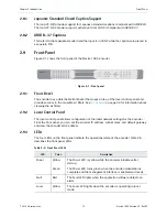
Page 15: ...e air filters See 5 1 Air Filters on page 33 for information about cleaning the air filters 2 9 2 Local Control Panel The local control panel allows configuration of the initial network settings for the encoder From the front panel you can set the encoder IP address subnet mask and default gateway and view the encoder MAC address 2 9 3 LEDs The four LEDs on the front panel indicate the operational...

Page 16: ...lassic display mode as well as channel name and bitrate For more information on the NMX control on the second line refer to the NMX online help 2 10 Back Panel The back panel contains the following elements as shown in Figure 2 2 NOTE Refer to Table C 1 on page 48 for information on which adapters cards modules are supported in your back panel Activity Yellow The Activity LED lights when the encod...

Page 17: ...ns 2 10 2 DC Power and Fuse If your encoder includes the optional DC power supply see Appendix E Wiring the 48 VDC Power Supply for more information about the power supply 2 10 3 Audio Input Ports Each AIC has two stereo analog audio input ports and two digital audio input ports BNC connectors The encoder supports up to five AICs Figure 2 3 illustrates the audio input ports on an AIC Figure 2 3 Au...

Page 18: ...el stops outputting and the backup channel takes over In manual redundancy you can enable one channel or both channels If you enable one channel you must manually switch to the other channel after a service affecting alarm If you enable both channels the encoder outputs the same data from both channels See 3 5 4 Connecting the IP Output Cables on page 25 for cabling instructions Set the IP address...

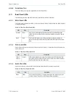
Page 19: ...LED located on each AIC Table 2 6 Rear Panel Main Board LEDs LED Color Description Locator Blue The Locator LED lights when this encoder is enabled through NMX Use the Locator LED to help you identify a specific chassis in a rack Fault Red The Fault LED lights when the application software detects an alarm The front panel and back panel Fault LEDs light at the same time Table 2 7 Rear Panel Video ...

Page 20: ...nt follow the unpacking instructions that come with the encoder When you unpack the encoder you should find the following items Encoder Standard IEC power cord Spare air filters Software warranty agreement Harmonic ships rack mounting kits in a separate shipping container 3 3 Installing the Encoder in a Rack You can install the encoder in different sizes and types of racks For rack assembly instru...

Page 21: ...tte unité en casier il convient de prendre des précautions spéciales afin de maintenir la stabilité du système Les directives ci dessous sont destinées à assurer la protection du personnel Si cette unité constitue la seule unité montée en casier elle doit être placée dans le bas Si cette unité est montée dans un casier partiellement rempli charger le casier de bas en haut en plaçant l élément le p...

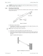
Page 22: ...s Figure 3 1 Rack rails To attach the rack rails to the rack 1 If needed place a Tinnerman speed nut with the nut on the outside of the rack over the holes to which you would like to mount the rails NOTE Each of the four rack posts requires two speed nuts 2 Position the rack rails so the shelves are toward the inside of the rack 3 Using the 10 screws provided with the encoder screw the mounts into...

Page 23: ...rack rails 3 Push the encoder back until the rack mount holes in the front of the encoder line up with the rack posts 4 Insert four screws through the mount holes in the front of the encoder through to the corresponding holes on the rack posts 5 Tighten the screws with a screwdriver 6 Carefully replace the front bezel of the encoder making sure you do not damage the air filters Figure 3 3 Mounting...

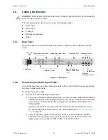
Page 24: ... one of the following audio sources Analog If you have an analog audio source connect the audio cable with the Phoenix 1881 367 connector to the analog audio port and connect the other end to the audio source device On the encoder the analog ports are labeled ANLG AUD1 and ANLG AUD2 Install the cable shield drain lug under the head of the AIC panel fastener screw For cable building information ref...

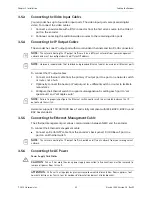
Page 25: ...lly connect the backup IP output port to a different switch or router to facilitate redundancy 3 Configure the Ethernet switch to support autonegotiation by setting each port to set speed auto and set duplex auto NOTE Failure to properly configure the Ethernet switch could result in a mismatch between the IP output and the switch Harmonic supports 10 100 1000 Base T and is fully compliant with IEE...

Page 26: ...ukt ist darauf angewiesen daß im Gebäude ein Kurzschluß bzw Überstromschutz installiert ist Stellen sie sicher daß eine Sicherung oder ein Unterbrecher von nicht mehr als 240 V Wechselstrom 20 A bzw in den USA 120 V Wechselstrom 20 A an den Phasenleitern allen stromführenden Leitern verwendet wird To connect the power cord Connect the power cord to the power plug on the encoder back panel and conn...

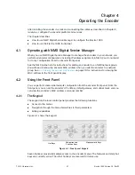
Page 27: ...will need to know the encoder MAC address when you add the encoder to a network group See 4 2 4 Viewing the Encoder MAC Address on page 29 for instructions for viewing the MAC address in the front panel display 4 2 Using the Front Panel You can perform some initial network configuration from the encoder front panel From the front panel you can set the encoder s IP address default gateway and subne...

Page 28: ...alue A steady cursor shows the value being edited Press the Help key to display an online message for the currently selected menu item 4 2 3 Setting the Encoder Network Properties Before you can begin to configure the encoder you must set the encoder IP address subnet mask and default gateway The encoder ships with a default IP address based on the encoder serial number The default subnet mask is ...

Page 29: ...WK hot key 2 Press the key several times to navigate to NTWK Control MAC The MAC address appears beneath the parameter name 3 Press Esc to exit the parameter 4 2 5 Viewing the Encoder Serial Number You can view the encoder serial number from the front panel To view the encoder serial number 1 Press the STAT hot key 2 Press the key to navigate to STAT Serial Number The serial number appears beneath...

Page 30: ... address as a site that allows pop ups To change the pop up window settings 1 Open Internet Explorer 2 From the Tools menu select Pop up Blocker If you do not see this menu item your version of Internet Explorer does not have this utility You can open Configuration Manager 3 If you do have this menu item select Turn Off Pop up Blocker to disable the utility or select Pop up Blocker Settings to ena...

Page 31: ...about items selected in the navigation pane Use this pane to apply configuration You can resize any pane by dragging the border of the pane up down left or right To begin configuring the encoder apply a template Templates contain basic settings for all encoder platform port and stream properties After applying a template customize the settings for your environment Click the Help button in the Stat...

Page 32: ...r the matching device feature and binds the license key to that encoder One lic file may contain multiple license keys Every key in the lic file will be applied One license key may unlock multiple instances of a feature There is no undo for applying licenses but you can delete them Delete a license key and save the deletion receipt for return to Harmonic If you want to remove a license key from on...

Page 33: ... 2 shows the keypad filter Figure 5 2 Keypad filter front view 5 1 1 Maintaining the Air Filters The operating environment of the encoder plays a large factor in determining the life of the air filters Encoders that operate in dusty and dirty surroundings require more frequent inspections and filter cleaning than those operating in cleaner environments Inspect and clean the filters with a frequenc...

Page 34: ...lter around the bezel mounting posts 6 Carefully replace the front bezel on the encoder making sure the filter does not fall out of the bezel 5 1 2 2 Removing and Replacing the Keypad Filter To remove the air filter from behind the keypad 1 Grasp each side of the encoder front bezel with your hands 2 Carefully remove the front bezel by pulling it away from the encoder Note the location of the filt...

Page 35: ...l the new fuse DANGER Always replace the fuse with a fuse of the same rating and type Using a different fuse voids the Harmonic warranty and could result in fire or other electrical damage 5 Replace the fuse cover 6 Plug in the encoder 5 3 Contacting Harmonic Support The Harmonic Customer and Technical Support groups are available to help you with any questions or problems you may have regarding H...

Page 36: ... 2012 Harmonic Inc 36 Electra 1000 Version 3 0 Rev M The corporate telephone numbers for Harmonic Inc are Tel 1 800 788 1 330 from the U S and Canada Tel 1 408 542 2500 outside the U S and Canada Fax 1 408 490 6708 The Web address for Harmonic Inc is www harmonicinc com ...

Page 37: ...Kbps MPEG 1 Layer II compression Single channel 1 0 32 kHz 44 1 kHz 48 kHz 32 48 56 64 80 96 1 1 2 1 28 160 192 Dual channel 1 1 Stereo channel 2 0 Joint stereo channel 32 kHz 44 1 kHz 48 kHz 64 96 1 1 2 1 28 160 192 224 256 320 384 MPEG 1 Layer II compression SPPC separate PID per channel Single channel 1 0 32 kHz 44 1 kHz 48 kHz 32 48 56 64 80 96 1 1 2 1 28 160 192 Dolby Digital AC 3 compression...

Page 38: ...ms are encapsulated as LATM LOAS and assigned a stream type value of 0x1 1 Encapsulation mode is controlled by selecting MPEG 2 or MPEG 4 as required 5 3 1 PCM Downmix from 5 1 This encoder has the ability to accept 5 1 PCM three pairs embedded on AES or embedded and create a downmix before 2 0 encoding Audio encoding is accomplished Onboard RAC or an AHC 561adapter Refer to the NMX online help fo...

Page 39: ... A 2 MPEG 1 Layer II Audio Bit Rates Audio Bit Rate Kbps Audio without PCR Audio with PCR 48 kHz 44 1 kHz analog only 32 kHz analog only 48 kHz 44 1 kHz analog only 32 kHz analog only 32 41 8 38 4 34 8 41 8 38 4 34 8 48 52 2 57 6 55 7 52 2 57 6 55 7 56 62 7 67 2 62 7 62 7 67 2 62 7 64 73 1 67 2 69 6 73 1 76 8 69 6 80 83 6 86 4 83 6 94 0 86 4 90 5 96 104 4 105 6 104 4 104 4 105 6 104 4 1 1 2 1 25 3...

Page 40: ... channel mode because the bit rate is the lowest available the encoder provisions to the next highest available bit rate 64 Kbps If you set the bit rate to 80 Kbps and then change the coding mode to non single channel the encoder provisions the bit rate to 64 Kbps Table A 3 Dolby Digital AC 3 Audio Bit Rates Audio Bit Rate Kbps Audio without PCR Audio with PCR 48 kHz 44 1 kHz 32 kHz 48 kHz 44 1 kH...

Page 41: ...ite input is used a high quality decoder converts the signal into ITU R 601 digital format Table 5 1 Video Specifications Feature Specification Comments Input formats Serial digital component and composite or analog composite Either 625 lines PAL or 525 lines NTSC Analog input level 1 V p p nominal Factory calibrated Analog input digitizing resolution 9 bits SNR 52 dB rms Unweighted Frequency resp...

Page 42: ...26 cm x 60 69 cm 1 75 in x 19 in x 24 in Weight 1 1 kg 24 lb AC Power Input voltage range AC 100 240V auto ranging Line frequency 47 to 63 Hz Typical consumption 47 W per video encoder 188 W with 4 video encoders Fuse 6 3 A 250V fuse 5 x20mm DC Power Nominal input 48 VDCManual Part No MAN ELECTRA7000 3 0MAN ELECTRA1000 3 0Harmonic DiviCom Electra 1000 MPEG 4 AVC Standard Definition Multiservice En...

Page 43: ... Hz 3 axis Table B 2 Port Specifications Port Connection Specification Video input port Protocol Serial Digital Signal format per SMPTE 259M Data stream format per ITUR BT 601 Composite Signal format per SMPTE 1 70M NTSC or PAL Data stream format per ITUR BT 470 Impedance 75 Ω unbalanced Connector type BNC Analog audio input Input Two analog or digital stereo pairs per AIC Impedance 10K Ω Mating c...

Page 44: ... on page 25 for cabling instructions Table B 3 lists the pinouts for the RJ 45 Ethernet port Ethernet management port Type 10 100 Base T Protocol 802 3 Connector type RJ 45 Input serial port Reserved for future use Ethernet output port Type 10 100 1000 Base T Protocol MPEG 2 over IP Connector type RJ 45 Fault relay port Capable of switching 0 25 amps at 30 VDC Mating connector type Phoenix 1881 38...

Page 45: ...o platforms that define the state of the platform by being either on or off Table B 4 lists the fault relay pinouts Individual wires need to be inserted into the contacts and grounded to the ground pin to activate a contact closure When configured in the DPI properties page of either NMX or the SAG an SCTE35 message is sent out when that pin is set to low Each is independent and can be provisioned...

Page 46: ...lectra 1000 Version 3 0 Rev M B 3 3 Analog Audio Input Ports Each analog audio port uses a Phoenix 1881 367 connector Table B 5 lists the cable connector pinouts Table B 5 Analog Audio Port Pinout Pin Description 1 Right 2 Chassis Gnd 3 Right 4 Left 5 Chassis Gnd 6 Left ...

Page 47: ...se the included Evertz cable to support External 708 closed captioning some pinout adjustments must be made to the cable Table 5 2 describes the proper orientation NOTE Connect Pin 5 on both the DB9 and HD15 to shell Also short pins 7 and 8 on the DB9 connnector Table 5 2 Evertz Cable Pinout Arrangement DB9 Connector HD15 Connector Pin 5 Pin 5 Pin 3 Pin 2 Pin 2 Pin 6 ...

Page 48: ...Table C 2 lists the card module configurations available for FLEX based encoders Table C 1 Supported cards modules and configuration recommendations for this encoder Card Module Slot Notes AIC Any slot 1 5 adapters per chassis AHC RAC Any slot 1 5 adapters per chassis AHC 561 Any slot 1 4 1 4 adapters per chassis Not supported on slot 5 ASI Output Slot 5 without a FLEX module Slot 2 with a FLEX mo...

Page 49: ...ntrol Board CPC link The Control Board CPC Configuration page appears 3 Click on the Maintenance tab to examine the version information ASI Input Slot 1 typical slot 3 if slot 1 is already in use 1 card per chassis For FLEX only chassis the FLEX module goes into slot 4 and 5 Slot 4 must be populated first For baseband and compressed mixed input encoders the FLEX module can be either slot 4 or 5 AS...

Page 50: ...splay on the vacuum fluorescent display VFD during a successful startup Power on VFD line 1 Harmonic Inc VFD line 2 System Loading Begin loading VFD line 1 Electra VFD line 2 System Loading Booting VFD line 1 Electra VFD line 2 Loading xxxxxxxx elf Finished VFD line 1 Electra VFD line 2 Multichannel Encoder D 2 Other Local Control Panel Display Messages The local control panel displays messages fo...

Page 51: ...ished VFD line 1 Electra VFD line 2 Multichannel Encoder D 2 2 Loading New Software You can download new software to an encoder using NMX After downloading the software restart the encoder to begin using the new software The following messages appear Begin loading VFD line 1 Electra VFD line 2 System Loading Booting VFD line 1 Electra VFD line 2 Loading xxxxxxxx elf Finished VFD line 1 Electra VFD...

Page 52: ...tive ground The Positive bus of the DC power source must be reliably connected to the Ground bus Each feed pair must provide a continuous supply of power that meets the specifications shown in Table E 1 E 3 Overcurrent Protection To provide overcurrent protection Provide overcurrent protection devices as part of each rack housing encoders Locate a readily accessible disconnect device between the D...

Page 53: ...el number 231 103 037 000 Use only the original connector for connecting the encoder to the DC power source Contact Harmonic Technical Support if you want to use any other type of connector Figure E 2 shows the connector and its strain relief housing Figure E 2 DC power connector Table E 2 DC Power Wire Requirements Parameter Specification Suitable conductor material Copper only Vin and Vin wires ...

Page 54: ... wire Stripping more leaves uninsulated wire exposed outside the DC connector after the assembly is complete 6 Insert a small screwdriver into the rectangular hole directly above the hole in the DC connector where you want to insert the first cable and press down on the screwdriver This opens the cage clamp for this section of the DC plug connector NOTE WAGO also sells tools specifically designed ...

Page 55: ...LEX module supports both ASI and IP inputs the most efficient interfaces used to route and transport pre compressed video feeds NOTE AHC 561 card is not supported for use with FLEX modules The FLEX module is controlled and configured with the NMX Digital Service Manager application or SAG the web based GUI The FLEX module also accepts decoded ATSC 8VSB signals from the RF Input card RF Input Card ...

Page 56: ...0 Specific hosts only ASI input and output available with FLEX module using two ASI cards Table F 2 Audio Passthrough Specifications Feature Support Number of channels 8 however the total passthrough bitrate per FLEX program cannot exceed 4Mbps Audio formats MPEG 1 Layer II Dolby Digital AC 3 and AAC audio passthrough MPEG 1 Layer II1 0 and 2 0 Dolby AC3 5 1 and 2 0 Audio processing Audio passthro...

Page 57: ...ations Up to 4 mono stereo decode streams per FLEX decoding port Up to one multichannel audio decode and one stereo decode stream per FLEX decoding port Up to 2 multichannel audio decode and 2 stereo audio decode streams on the first FLEX decoding port Up to 8 mono stereo decode streams on the first FLEX decoding port with no audio on second port See Table F 4 on page 58 for information on AC 3 re...

Page 58: ...annel No Audio on the Center channel Silence on all others 3 x Stereo Stereo Mon Available irrelevant for this decoding mode Audio on the left channel Silence on the right channel Stereoa Stereo Audio on both channels Multichannel No Audio on both left and right channels Silence on all others 3 x Stereo AC 3 continued Multichannel Mono Available must be enabled for this decoding mode or an alarm i...

Page 59: ...ed by the FLEX module F 6 Input Specifications Table F 7 describes the input specifications FLEX module a Enabling Multichannel downmixing allocates resources for downmixing resulting in resource usage equivalent to 3 x Stereo Table F 5 MPEG L2 Resource Considerations Input Format Audio Input into card Decoding Mode Result Resource Usage Equivalent MPEG 1 Layer II Mono Mono Audio on left channel S...

Page 60: ... Bit Rate per Socket 80 Mbps Addressing Unicast and multicast Management IGMP ARP and ICMP Forward Error Correction FEC The FLEX module supports SMTE 2022 Annex C forward error correction FEC FEC provides lost packet recovery at the receiving devices RF Input Card For specifics see Appendix G on page 74 Table F 8 Outputs Specifications Feature Support Video Outputs One 1 per decoded channel with v...

Page 61: ...electrostatic discharge ESD follow these safety precautions Always wear a properly grounded antistatic wrist strap whenever handling the modules Keep the module inside the antistatic bag until you are ready to install the module in a chassis F 10 1 Installing a Module Before installing the FLEX module you may need to upgrade the software version on the encoder Contact Harmonic Customer Support to ...

Page 62: ...e new FLEX module in the encoder s configuration F 11 Cabling the FLEX Module This section describes how to cable the FLEX module Cabling the FLEX module is very straight forward All video and monitor ports are clearly marked The following table lists the ports and required connectors NOTE Video ports can either be used for loopback or confidence monitoring Each firmware license ships with two vid...

Page 63: ...epresent Figure F 3 LED Color Chart Video 1 75 Ω cable DIN 1 0 2 3 Monitor 1 75 Ω cable This output port is used for the loopback cable that feeds an encoder DIN 1 0 2 3 Video 2 75Ω cable DIN 1 0 2 3 Monitor 2 75 Ω cable The second output port can be used as a monitoring and troubleshooting purposes DIN 1 0 2 3 Table F 9 Port and Cable Assignments 2 channel IP Module Audio Module Audio Module FLEX...

Page 64: ...he NMX online help system for configuring a FLEX module for use in your NMX Digital Service Manager application Table F 10 Port and Cable Assignments Port Description Connector Video 1 75 Ω cable DIN 1 0 2 3 Monitor 1 75 Ω cable This output port is used for the loopback cable that feeds an encoder DIN 1 0 2 3 Video 2 75Ω cable DIN 1 0 2 3 Monitor 2 75 Ω cable The second output port can be used as ...

Page 65: ...SAG Figure G 1 on page 65 shows a diagram of the rear panel Figure G 1 RF Input card The LED lights show status as shown in Table G 1 on page 65 G 1 RF Specifications The RF specifications for the card are listed below VSB Input 4 Type F connectors per IEC 60169 24 Tuning Range VHF UHF Channels 2 59 NOTE Tuning range is limited to Channels 2 to 59 by software per the FCC Industry Canada decisions ...

Page 66: ...Rev M G 2 Output Specifications The output specification for the aapter is Four MPEG 2 Transport Streams per ATSC A 53 Part 3 and ISO IEC 1 3818 1 G 3 Environmental and Physical Compliant with ROHS Directive 2002 95 EC Refer to the encoder environmental specifications for additional information ...

Page 67: ...line A input to the Line B input or the reverse upon loss of power on the active line The A B Power Input Switch uses and monitors the active line continuously and switches to the backup port only when the active line has a fault The unit switches back automatically when the active port is detected as normal and stable with an appropriate delay NOTE The A B Power Input Switch is a dual height card...

Page 68: ...ommended that you use A for primary equipment and B for backup equipment The LED lights show card status as shown in Table H 1 on page 68 Table H 1 LED status lights Display Status Red Input power for that port is not within the acceptable voltage range Green Steady input power for that port is within acceptable voltage range Flashing port is being utilized for input power Orange Port failure can ...

Page 69: ...dio input 43 digital audio input 17 43 Ethernet 18 44 fault relay 45 IP output 18 RJ 45 18 44 video 43 cTUVus North American safety approval 4 D DC power supply 17 52 digital audio connecting 24 port specifications 43 ports 17 digital program insertion 14 display front panel 28 DiviTrack IP 13 Dolby Digital AC 3 bit rates 39 DPI 14 E environmental specifications 42 Ethernet management port connect...

Page 70: ...8 serial data 19 video input 18 power supply AC 25 DC 52 specifications 42 R rack mounting 20 rack rails attaching 22 rack mount kit 20 replacing air filters 34 resetting the encoder 50 RJ 45 connectors 18 44 S serial data port 19 specifications environment 42 fuse 42 hardware 42 input and output 43 port 43 power supply 42 video 41 standards and approvals 4 T TUV European safety approval 4 U unpac...

Page 71: ...Harmonic Inc 4300 North First Street San Jose CA 95134 U S A T 1 408 542 2500 F 1 408 490 6708 www harmonicinc com Copyright 2012 Harmonic Inc All rights reserved Manual Part No MAN ELECTRA1000 3 0 ...

Reviews: