Harman P43-C Installation Manual Download Page 10

Harman®  •  P-Series Installation Manual_R3  •  2018 - ___  •  09/20

10

8390-044I

C.  Floor Protection

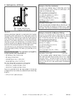
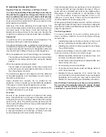
Parallel Installation:

Place  the  stove  on  a  noncombustible  type  floor  or  floor 

protector that extends a minimum of 6 inches (152mm) to 

the front of the load door opening, 6 inches (152mm) to the 

sides of the door opening, and 6 inches to the rear.

The P-Series does not require R value floor protection.
The minimum floor protector material is 20 gauge sheet metal. 

Other floor protector materials that can be used include Type 

I hearth pads, ceramic tile, stone, brick, etc. Figure 3.3

*Floor protection dimensions for the front and sides are 

measured from the appliance door opening in The United 

States. In Canada, the side dimension is measured from the 

widest part of the appliance.

P43-C

  -  Minimum  size  rectangular  floor  protection  is  25-

7/16” Wide by 26-3/4” Deep (646mm X 680mm).

P61-C

 - Minimum size rectangular floor protection is 25-1/8” 

Wide by 27-3/4” Deep (638mm X 705mm).

P68-C

  -  Minimum  size  rectangular  floor  protection  is  25-

3/16” Wide by 27-3/4” Deep (640mm X 705mm).

Venting:

US

 - 

Follow PL vent manufacturers recommendations when 

configuring vent pipe installation

.

Canada

 - Must extend 2” (51mm) beyond each side of any 

horizontal flue pipe.

Figure 3.3

J

K

L

Floor Protector

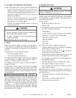
D. Mobile Home Installation

When installing this unit in a mobile home, several 

requirements must be followed: 
1. 

The unit must be bolted to the floor. This can be done 

using an appropriate fastener for the application.

2. The unit must also be connected to o

utside air. See 

Termination Location and Vent Information” Section D

.

3. Floor protection and clearances must be followed as 

shown.

4. 

The appliance must be properly grounded to the frame of 

the mobile home using a minimum of 8 AWG copper solid 

or stranded, insulated or bare wire or equivalent.

Floor Protection 

Requirements

US

Canada

J

Sides

6"

152mm

K

Front

6”

152mm

L

Rear

6”

152mm

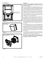
Corner Installation:

Minimum size floor protection for a corner installation hearth 

pad is:

P43-C

 - Minimum size floor protection is 25-7/16” Wide by 

26-3/4” Deep (646mm X 680mm).

P61-C

 - Minimum size floor protection is 25-1/8” Wide by 

27-3/4” Deep (638mm X 705mm).

P68-C

 - Minimum size floor protection is 25-3/16” Wide by 

27-3/4” Deep (640mm X 705mm).

Note: Floor protector WILL NOT touch the wall using 

minimum clearances.

If  corner  floor  protection  is  desired  to  touch  the  wall,  the 

floor protection will need to be at least 40” x 40” (1016mm 

x 1016mm). 

Note: This will allow the floor protection to 

touch the wall as shown. Figure 3.4

.

Alternate floor protector dimension may be used as long as 

they satisfy the measurement requirements shown below.

Figure 3.4

Summary of Contents for P43-C

Page 1: ...y ignite clothing or other flammable materials Keep clothing furniture draperies and other flammable materials away HOT SURFACES Glass and other surfaces are hot during operation AND cool down WARNING...

Page 2: ...n Combustible Materials Specification 5 G Combustible Materials Specification 5 H Electrical Codes 5 2 Getting Started A Design and Installation Considerations 6 B Tools and Supplies Needed 7 C Inspec...

Page 3: ..._______________________ Electrical Section 1 120 VAC unswitched power provided to the appliance ________________________________ Check outlet with multi meter for proper voltage 115 120 VAC __________...

Page 4: ...135PS023E 0135PS023S TYPE Pellet Fueled Supplementary For Residential Use STANDARD s ASTM E 1509 04 ULC S627 00 ASTM E 2515 11 ASTM E 2779 10 MODEL P61 C Pellet Stove LABORATORY OMNI Test Laboratories...

Page 5: ...any component not approved by Hearth Home Technologies Install parts or components not Listed or approved Disable safety switches Improper installation adjustment alteration service or maintenance ca...

Page 6: ...r Intakes Air Conditioner Overhang soffits porch roofs adjacent walls Landscaping vegetation Marginal Location Below peak Location NOT recommended Not the highest point of the roof Wind loading possib...

Page 7: ...be voided by the following actions Installation and use of any damaged appliance or vent system component Modification of the appliance or vent system Installation other than as instructed by Hearth H...

Page 8: ...tual appliance dimensions Use for reference only Figure 3 1 20 3 4 22 10 33 1 2 5 1 8 13 3 4 28 5 16 Outside Air Intake P43 C Freestanding Pellet Stove 23 1 2 10 36 1 2 5 1 8 13 3 4 29 3 8 Outside Air...

Page 9: ...placed on or near this unit B Clearances to Combustibles When selecting a location for the appliance it is important to consider the required clearances to walls Figure 3 2 CAUTION THIS APPLIANCE MUST...

Page 10: ...ipe Figure 3 3 J K L Floor Protector D Mobile Home Installation When installing this unit in a mobile home several requirements must be followed 1 The unit must be bolted to the floor This can be done...

Page 11: ...vent of a power failure Do not place joints within wall pass through 2 Preferred method Figure 4 2 This method also provides excellent venting for normal operation but requires the stove to be install...

Page 12: ...sting fireplace chimney Figure 4 4 This method provides excellent venting for normal operation This method also provides natural draft in the event of a power failure If the chimney condition is quest...

Page 13: ...this method a cap should also be installed on the chimney to keep out rain Be sure to use approved pellet vent pipe fittings Pipe size should be increased to 4 using this method 6 Installing into an...

Page 14: ...wall pass through Figure 4 7 Figure 4 8 Figure 4 9 Area within dotted circle represents the minimum clearance to combustible materials such as shrubbery mulch or tall grasses 12 min above ground level...

Page 15: ...ide corner is 11 from center of pipe G The clearance to an inside corner is 12 H A vent must not be installed within 3 feet 90 cm above a gas meter regulator assembly when measured from the horizontal...

Page 16: ...ositive static pressure Negative static pressure O Figure 4 11 Example First Floor Installation A unit is to be installed using 3 Pellet Pipe with 3 feet of horizontal pipe a Tee 10 feet of vertical p...

Page 17: ...10 Ft 15 Ft 20 Ft 25 Ft 30 Ft 5 Ft 0 Ft 15 Ft Equivalent Vent Length EVL Maximum Horizontal Run Long runs of flex or PL vent pipe installed directly vertical from the flue stub may require more freque...

Page 18: ...he stove especially during a power failure It may be necessary to add additional ventilation to the space in which the pellet appliance is located Consult with your local HVAC professional to determin...

Page 19: ...windows in the home are closed Record the second draft reading _______ If the second reading is more than 05 lower than the first reading check for possible restrictions or the need for outside air Fo...

Page 20: ...pass through fittings to go through combustible walls and ceilings Be sure to use a starting collar to attach the venting system to the stove The starting collar must be secured to the flue stub with...

Page 21: ...pliance Modification of the appliance Installation other than as instructed by Hearth Home Technologies Installation and or use of any component part not approved by Hearth Home Technologies Operating...

Page 22: ...t contact with hot or moving parts If needed install the 2 5 16 18 X 3 4 leveling bolts located in the hardware kit Figure 5 1 C Firebrick The P43 C Pellet Stove has a single 1 firebrick that gets ins...

Page 23: ...stment should be done by the installer during set up because a draft meter reading is required to insure proper set up If the unit is not adjusted properly it does not cause a safety concern If the un...

Page 24: ...HOME FLOOR WALL AND CEILING ROOF MUST BE MAINTAINED CAUTION Due to high temperatures this stove should be placed out of traffic and away from furniture and draperies Children and adults should be aler...

Page 25: ...E PRESSURE SWITCH NO CONTACTS COMBUSTION MOTOR FEED MOTOR IGNITER ELEMENT P43 P61 P68 DISTRIBUTION BLOWER WHITE OR LT BLUE GREEN USED ON ACCENTRA ONLY DK BLUE OR BLACK ACCENTRA P35i P40i XXV DISTRIBUT...

Page 26: ..._ 09 20 26 8390 044I 352 Mountain House Road Halifax PA 17032 www harmanstoves com Please contact your Harman dealer with any questions or concerns For the location of your nearest Harman dealer pleas...

Reviews: