6
11. OK
•
Press to confirm your selection.
12.
•
Toggle Optical / Aux as an input source.
13. Microphone
4 INSTALLATION
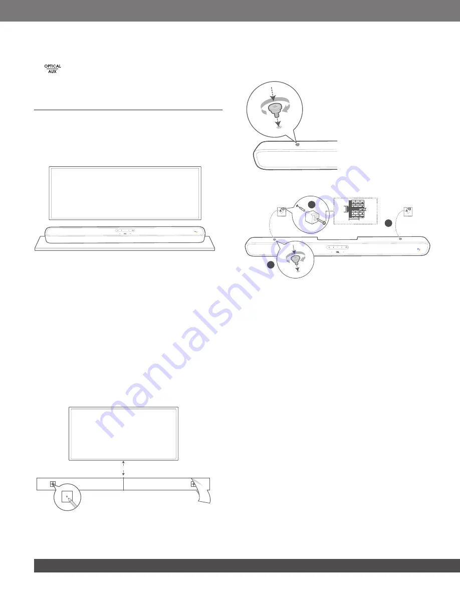
4.1 Place the LINK BAR on the table
Place the LINK BAR on its rubber feet on a stable and level
surface.
TV
NOTES:
−
Remove any interference from both sides of the LINK BAR so the side-
firing bass port can react correctly.
−
To avoid wireless interference, keep other wireless devices 1-3ft (0.3-
0.9m) away from the LINK BAR.
−
Make sure there is an AC outlet nearby.
−
Do not place any objects on the top of the LINK BAR.
4.2 Wall-mount the LINK BAR
1.
Use tape to stick the wall-mount paper guide on the wall, push
a pen tip through the center to mark the wall-mount bracket
location and remove the paper.
2.
Keep a minimum distance of 2” (50mm) for TV clearance.
3. Use an appropriately sized drill bit, drill a hole in the wall at
each pen marking.
TV
2-D=4mm
Min. 2” (50mm)
4.
Screw the wall mount brackets on the pen mark.
5.
Screw the threaded mounting post into the back of the LINK
BAR.
6. Hook the LINK BAR to the brackets attached to the wall.
3
≤8 mm/
0.31"
4mm/
0.16"
≥35 mm/1.4"
1
2
NOTES:
−
Before mounting on a wall, make sure the wall can support the weight
of this unit.
−
Install on a vertical wall only.
−
For the wall-mounting, avoid a location with high temperature or
humidity.
−
Connect cables from the unit to the external devices before installing
on the wall.
−
Make sure the power cord is unplugged from the AC outlet before the
installation. Otherwise, it may cause an electric shock.
−
Before connecting the power cord to your LINK BAR to the wall outlet
make sure all connections between components are connected.
−
Before moving the unit, make sure to unplug the power cord first.
Summary of Contents for JBL LINK BAR
Page 1: ...LINK BAR OWNER S MANUAL ...


