background image

R131

2K

R144

1K

C137

47uF/25V

Q103

2SC1815

R135

47R

R139

6K8

R134

47R

Q102

2SC1815

Q105

2SC1015

Q104

2SC1015

R137

47R

R136

47R

R138

6K8

Q109

667

Q108

MPSA13

C135

CM104

R147

3K3

R148

5K6

Q106

2N5401

Q107

2N5551

C131

100P

R146

47R

R149

47R

C132

100P

R165

0.15/5W

R156

680R

D101

IN4148

R159

6K8

Q113

2SC1815

C136

104

Q110

647

R155

0.15/5W

R157

680R

D102

IN4148

R160

6K8

R158

4R7/1W

C158

104

C133

47P

R145

11K

R151

220R/0.5W

+VCC

R170

1K

R168

10K

R169

1K

R175

33K

R166

3K

R231

2K

R244

1K

C237

47uF/25V

Q203

2SC1815

R235

47R

R239

6K8

R234

47R

Q202

2SC1815

Q205

2SC1015

Q204

2SC1015

R237

47R

R236

47R

R238

6K8

Q209

667

Q208

MPSA13

C235

CL104

R247

3K3

R248

5K6

Q206

2N5401

Q207

2N5551

C231

100P

R246

47R

R249

47R

C232

100P

R265

0.15/5W

R256

680R

D201

IN4148

R259

6K8

Q213

2SC1815

C236

104

Q210

647

R255

0.15/5W

R257

680R

D202

IN4148

R260

6K8

R258

4R7/1W

C258

104

C233

47P

1

2

R245

11K

R251

220R/0.5W

+VCC

-VCC

R270

1K

R268

10K

R269

1K

R275

33K

R266

3K

LCH

RCH

R133

33K

R233

33K

-VCC

Q111

718

Q211

718

Q212

688

Q112

688

Q102P

STN3904S

Q103P

STN3904S

R158P

6K8

C142P

100uF/25V

D101P

IN4148

1

2

3

4

JK1

REAR

R132

56K

R232

56K

C192B

CW 10u/50V

C192A

CW 10u/50V

R140

220R/0.5W

R240

220R/0.5W

C17

CL224

C18

CL224

R24

51K

C22

220U/16V

R30

6K8

D25

1N4148

Q17A

2SC1815

Q16

2SC1815

D9

1N4148

R23A

51K

RCH

LCH

C300

100p

C301

100P

C302

100P

C303

100P

D203

IN4148

D103

IN4148

C2

122

C3

122

R3B

PTC NC

R3A

PTC NC

R4B

270R

R4A

270R

152

改为

122

152

改为

122

R31

6K2

PROT

J24
20mm

PROT

J21

20mm

J20

20mm

J23

20mm

J22
20mm

J28

10mm

J29

10mm

PROT

J31

10mm

J32

10mm

J33

12mm

PROT

J34
15mm

PROT

C142P1

100uF/25V

J35
6mm

J36
6mm

J37

10mm

J38

10mm

J39
7.5mm

J40
6mm

R

L

J53
6mm

J54

10mm

-AMP1

-AMP

+AMP

+AMP1

J55

10mm

J56
10mm

J57
10mm

J58
10mm

J59

20mm

J61
15mm

J60
15mm

J62
12mm

J65

10mm

J64

10mm

J63

15mm

J66

6mm

J67

7.5mm

J74
12mm

J75
7.5mm

J77

12mm

J78
7.5mm

PROT

C23

CL222(NC)

C25

CL222(NC)

J80
7.5mm

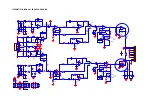
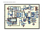
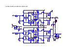
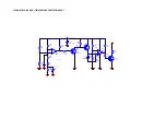
SCHEMATICS DIAGRAM - 

MAIN BOARD - 

AMPLIFIER 

 PART

Summary of Contents for JBL GX-A422SI

Page 1: ...y 2015 Harman Consumer Group Inc Rev 1 0 03 2015 8500 Balboa Boulevard Northridge California 91329 OWNER S MANUAL 2 SCHEMATICS DIAGRAMS 18 LAYOUT DIAGRAMS 22 SET BLOCK DIAGRAM 16 PACKAGING INSTRUCTION...

Page 2: ...GX A422SI power amplifier OWNER S MANUAL...

Page 3: ...o not attempt the installation yourself Instead please ask your authorized JBL car audio dealer about professional installation INSTALLATION WARNINGS AND TIPS IMPORTANT Disconnect the vehicle s negati...

Page 4: ...t of backseat passengers or shifting cargo in the trunk Mount the amplifier so that it remains dry never mount an amplifier outside the car or in the engine compartment MOUNTING THE AMPLIFIER NOTE You...

Page 5: ...pe of screw terminals for power and speaker connections This type of terminal is easy to use and allows the easy connection of large gauge wire To use the connectors use a Phillips screwdriver to loos...

Page 6: ...e within 18 46cm of the battery s terminal Do not install the fuse in the holder at this time 3 Route this wire to the amplifier s location and connect it to the amplifier s 12V terminal Be sure to us...

Page 7: ...on the speaker IMPORTANT Make sure the and bare wires do not touch each other or the other terminal at both the amplifier terminals and speaker terminals Touching wires can cause a short circuit that...

Page 8: ...t The Crossover Controls on page 10 for information about setting the amplifier s controls USING THE SPEAKER LEVEL INPUTS If your source unit doesn t have line level outputs you can use the included s...

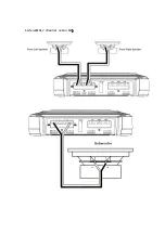
Page 9: ...provides a single high power channel for a subwoofer Minimum speaker impedance 4 ohms Connect the subwoofer to the RL and RR terminals NOTE You can connect two 2 ohm subwoofers in series to maintain t...

Page 10: ...on below NOTE Use a Y adapter to connect the source unit to the amplifier s left and right input jacks L L R R Source Unit Y Adapter Subwoofer Output See Set The Crossover Controls on page 10 for info...

Page 11: ...lifier to a pair of large full range speakers 6 x 9 or larger that can handle significant bass and you are not using a subwoofer in the system set the Crossover Filter switch to the FLAT full range po...

Page 12: ...n one amplifier repeat Steps 3 4 for all remaining amplifier Level controls SET THE BASS BOOST When you re using the amplifier in bridged mode to power a subwoofer the Bass Boost switch can provide 12...

Page 13: ...and speaker connections have been properly made Check that the amplifier s Level controls are not turned all the way down counter clockwise Check that the vehicle audio system s source unit s volume...

Page 14: ...enter midpoint positions Sound is too quiet even with the vehicle audio system s source unit volume all the way up Check that the amplifier s Level controls are not turned too low See Set The Input Le...

Page 15: ...THD 110W x 1 THD N at rated power 1 Signal to noise ratio rated output 4 ohms 93dB Effective damping factor 4 ohms 50 Frequency response 1dB 20Hz 20kHz 1dB Maximum input voltage 20V Maximum input sens...

Page 16: ...Power Amplifier input selector variable crossover 1 2 3 4 HI IN Pitch 2 5mm A bass boost 45Hz 0 12dB B5 INPUT SENS 0 2V 4V crossover 80Hz 12dB oct B1 B2 B3 HP LP pass B4 LP FLAT B6 4R out 2 4 R input...

Page 17: ...1 GX A422SI 4 2 2 channel or...

Page 18: ...220R R14B 220R R19B 22K C24B CC471 2 3 1 8 4 U5A 4560 6 7 5 8 SW2B SW2P3T C11D CL333 C23D CL333 R17B 82K R29B 43K R18B 220R 6 5 7 U4B 4560 R15B 220R FL HI 80Hz LP 80Hz FL LP 80Hz FL FULL 6 5 7 U3B 45...

Page 19: ...4 U2PA 4560 6 5 7 U2PB 4560 R40 4 7R R39 10K R38 4 7R R37 10K C60 104P R16P 2 2K RB6 13K R171P 12K C82 47uF 25V C79 104 R20P 47K R138P 2K C81 104 C84 104 C124P 104 R200P 2K R46 220R RB4 22K R61P 100K...

Page 20: ...104 C233 47P 1 2 R245 11K R251 220R 0 5W VCC VCC R270 1K R268 10K R269 1K R275 33K R266 3K LCH RCH R133 33K R233 33K VCC Q111 718 Q211 718 Q212 688 Q112 688 Q102P STN3904S Q103P STN3904S R158P 6K8 C14...

Page 21: ...1 2N3906 Q2 2SC1815 6 5 7 U1B LM393 1 5V R60 10K R67 47K R59 2 7K R58 7 5K R57 10K R61 47K R62 2 2K R63 2 2K Q3 2SC1815 C29 47uF 16V to 7 7 TL 494 15 to7 7 TL494 13 C39 104 A 62 1 5V R9 560K NTC1 20K...

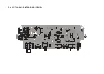
Page 22: ...PCB LAYOUT DIAGRAM FRONT END BOARD TOP VIEW...

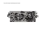
Page 23: ...PCB LAYOUT DIAGRAM FRONT END BOARD BOTTOM VIEW...

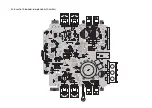
Page 24: ...PCB LAYOUT DIAGRAM MAIN BOARD TOP VIEW...

Page 25: ...PCB LAYOUT DIAGRAM MAIN BOARD BOTTOM VIEW...

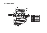
Page 26: ...End Board Amplifier Board Rear Panel Front Panel Logo Plate Heat Sink Decorative Plate Description Qty Part Number Item Screw PM3 4MM Screw PT3 8MM Screw 3 6MM Screw Mica Sheet SET MECHANICAL EXPLODED...

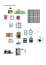
Page 27: ...Packaging Instructions Part Number Description QTY Main Unit S N Label EPE Foam Bag PE Foam PE Foam Cable Screws User Manual Beauty Box Carton Box PE Bag Label PE Bag...

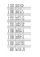
Page 28: ...3000147 Capacitor 101 50V 0603 NPO 5 26 020113000068 Capacitor 101 50V 0805 NPO 5 27 020123000164 Capacitor 104 50V 0603 X7R 10 28 020133000071 Capacitor 105 25V 0603 X5R 10 29 020133000041 Capacitor...

Page 29: ...8 010103000342 Resistor 6 8K 1 10W 5 0603 79 010103000535 Resistor 6 8K 1 8W 1 0805 80 010103001157 Resistor 6 8K 1 4W 1206 1 81 010103001060 Resistor 7 5K 1 8W 0805 1 82 010103000761 Resistor 8 2K 1...

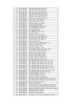
Page 30: ...103000044 Resistor 1 2K 1 10W 1 0603 135 010103000185 Resistor 3K 1 10W 1 0603 136 010103000412 Resistor 1 2K 1 8W 5 0805 137 020603000018 ceramic capacitor 104 100V 20 138 020733000027 Metal film cap...

Page 31: ...M 175 JD0101000025 Spring gasket D6 6 D4MM 1 0MM 176 JD0201000040 Mica plate 22 18 0 1MM 177 LS0101000104 screw BM 4 14 178 BZ0302000017 PE bag 90 60 0 05MM 179 BZ0202000391 pearl cotton L245 W90 H85m...

Reviews: