background image

14

Inlet Cover part# 1-10-08542

Flex pipe part# 1-00-08543

uSE 3 or 4 inch Pellet vent pipe- (Type Pl)

A combustion blower is used to extract the combustion 

gases from the firebox. This causes a negative pressure 

in the firebox and a positive pressure in the venting 

system as shown in fig. 19. The longer the vent pipe 

and more elbows used in the system, the greater the 

flow resistance. Because of these facts we recommend 

using as few elbows as possible and 15 feet or less 

of vent pipe. The maximum horizontal run should not 

exceed 48". If more than 15 feet of pipe is needed, the 

diameter should be increased from 3" to 4". 

be sure to 

use approved pellet vent pipe wall and ceiling pass-

through  fittings  to  go  through  combustibles. 

Be 

sure to use a starting collar to attach the venting system 

to the stove. 

All joints for connector pipe must be 

fastened with a minimum of three screws. Follow 

pellet vent manufacturer instructions for properly 

securing each pellet vent joint. The pellet starting 

collar must be secured to the unit's flue collar. 

Outside air is necessary in mobile homes and where 

building codes require.  The benefit of outside air is 

mainly noticed in small, very tight houses. 

To  install  outside  air  use  2  3/8"  I.d.  flex  pipe  part 

number 1-00-08543. There is a break-away hole on the 

rear panel which must be removed before connecting 

the  flex  pipe.  The  pipe  should  be  run  outside  and 

terminate to the side or below the vent pipe outlet so 

the flue outlet is more than 12" from the inlet cover. The 

maximum length run of this pipe is 15 feet. If a longer 

run is needed, the size must be increased to 3". Inlet 

cover part number 1-10-09542 should be used to keep 

birds, rodents, etc. out of  pipe.  

venting

Pellet  venting  pipe  (  also  known  as  PL  vent  )  is 

constructed of two layers with an air space between the 

layers. This air space acts as an insulator and reduces 

the outside surface temperature to allow a clearance 

to combustibles of only 3 inches or less. The sections 

of pipe lock together to form an air tight seal in most 

cases; however, in some cases a perfect seal is not 

achieved. For this reason and the fact that the Advance 

operates with a positive vent pressure, 

we specify that 

the joints also be sealed with silicone.

INSTAll vENT AT ClEArANCES SPECIFIEd 

bY ThE vENT mANuFACTurEr.
ChImNEY CONNECTOr mAY NOT PASS Thru 

AN ATTIC, rOOF SPACE, ClOSET, FlOOr, Or 

CEIlINg.

vent Pipe

Outside Air

Fig.19

direct vent wall Passthrough

The harman direct vent wall Passthrough (Part # 1-00-

677077) makes installing your harman Pellet Stove 

with outside air much easier. It is made to fit walls 

from 4 1/2" up to 10 1/8" thick with a square opening 

of 6" to 6 1/2". 

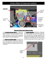
Outside air flex pipe 

goes here

Room Sensor 

Connection Ports

Outdoor Half

Indoor Half

+

+

-

= Positive static pressure

= Negative static pressure

+

-

Summary of Contents for Advance Pellet Stove

Page 1: ...YOUR SAFETY FOLLOW INSTALLATION DIRECTIONS CONTACT LOCAL BUILDING OR FIRE OFFICIALS ABOUT RESTRICTIONS AND INSTALLATION INSPECTION REQUIREMENTS IN YOUR AREA Contact your local authority such as munic...

Page 2: ......

Page 3: ...Do not install appliance in a sleeping room An outside combustion air inlet must be provided The structural integrity of the manufactured home floor ceiling and walls must be maintained Refer to manu...

Page 4: ...generally on 4 can be increased if higher burn rates are necessary The unit s maximum burn rate should not create less than 1 of ash on the burn pot front edge See Fig 2 Page 5 Overfeeding is not a sa...

Page 5: ...he unit to burn for about 30 minutes and check ash on front of burn pot Fig 2 If the ash line is larger than 1 turn the feed adjuster from 4 to 5 Allow another 30 minutes of burn time and check again...

Page 6: ...Manual position after the ignition cycle begins The difference between AUTO Room Temperature Mode and Manual Room Temperature Mode is that the fire will not go out as the room temperature goes above...

Page 7: ...pot Fig 5 If the ash line is larger than 1 turn the feed adjuster from 4 to 5 Allow another 30 minutes of burn time and check again If at 6 setting a 1 or less ash bed is not obtainable it is not a pr...

Page 8: ...for more details A six blink status may be set if the stove is allowed to run out of pellets To reset turn mode selector to OFF then back on to the desired mode If the unit was not out of pellets see...

Page 9: ...en cleaning or servicing Please take this into account when placing the stove Installation When installing this stove in a mobile home several requirements must be followed 1 The unit must be bolted t...

Page 10: ...shield Using a 5 16 nut driver or socket loosen the 2 screws about 4 or 5 turns Figure 12 Slide the rear shields straight outward until the ends come out of the rear retaining clips as seen in Fig 13...

Page 11: ...y efficiency is lost If the unit is adjusted too low the low draft pressure switch will not allow the feeder motor or the igniter to operate A simple draft test should be performed after completing th...

Page 12: ...than 25 feet from the unit or in another room are not recommended It is recommended that the room sensor be installed even if only installed on the rear of the unit as a return air sensor The room sen...

Page 13: ...ide air connection will supply the demands of the pellet appliance but consideration must be given to the total house demand House demand may consume some air needed for the stove especially during a...

Page 14: ...rear panel which must be removed before connecting the flex pipe The pipe should be run outside and terminate to the side or below the vent pipe outlet so the flue outlet is more than 12 from the inle...

Page 15: ...tion and allows the stove to be installed closest to the wall One inch from the wall is safe however two or three inches allows better access to remove the rear panel The vertical portion of the vent...

Page 16: ...aowool mineral wool or an equivalent non combustible insulation is recommended to be installed on top of the sealing plate to reduce the possibility of condensation Acap should be installed on the chi...

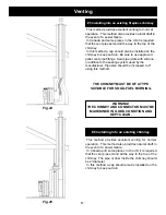
Page 17: ...ould be increased to 4 using this method This method provides excellent venting for normal operation This method also provides natural draft in the event of a power failure In Canada and some places i...

Page 18: ...min 3 min 3 min Fig 26 3 min It is recommended that outside air be installed with this venting configuration CAUTION Keep any materials that may be affected by the elevated exhaust temperatures at le...

Page 19: ...m above a gas meter regulator assembly when measured from the horizontal center line of the regulator 1 I The clearance to service regulator vent outlet must be a minimum of 6 feet 1 J The clearance t...

Page 20: ...A ROOM DESIGNATED FOR SLEEPING WARNING Keep combustibles away from flue outlet CAUTION CAUTION THE STRUCTURAL INTEGRITY OF THE MOBILE HOME FLOOR WALL AND CEILING ROOF MUST BE MAINTAINED Keep combustib...

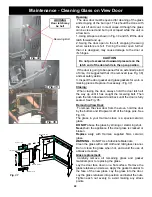
Page 21: ...ig 32 Fig 33 Maintenance Emptying Ashes Formation and Need For Removal The products of combustion will contain small particles of fly ash The fly ash will collect in the exhaust venting system and res...

Page 22: ...skets for worn or missing pieces Replace if necessary Fig 37 Closing When closing the door always hold the door latch all the way up until it has caught the receiving bolt Then push the latch downward...

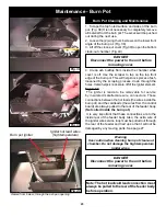
Page 23: ...leads the wires inside the burn pot and the cold leads the wires from the control board are always pulled to the rear of the feeder body Not coiled inside the burn pot It is very important that these...

Page 24: ...el into the left corner of the firebox with the panel resting on the top edges of the burn pot Rotate the right side of the brick panel through the door opening Reverse this operation to reinstall the...

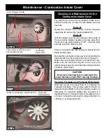
Page 25: ...l the combustion intake cover by first sliding the right side tab into the retainer slot seen in Figure 47 Rotate the cover inward until the cover fits into its hole Make sure the two faces Fig 46 of...

Page 26: ...t and left baffle are interchangeable 6 Now remove the heat exchanger baffle plates See Fig 50 51 To remove the left plate slide the center lock to the right To remove the right plate slide the center...

Page 27: ...d igniter circuits This is to protect against reaching into the feed mechanism while in operation The Control Board ESP combination is responsible for all high limit safety control There are 2 high li...

Page 28: ...rol board status indication is caused by poor or incomplete combustion The circuit board has the ability to track the combustion through feed settings and ESP temperatures When the control board has c...

Page 29: ...takes energy to dry and tends to cool the appliance thus robbing heat from your home Damp pellet fuel could turn back into sawdust which does not flow properly through the feed system Size Pellets are...

Page 30: ...e 2 3 8 inches Fuse Rating 6 amp BTU Range 0 to 48 000 Feed Rate 1 0 lbs hr on minimum 6 lbs hr on maximum Flue Size 3 inch Pellet Vent Pipe Maximum Wattage 480 Watts Start cycle and test Start Cycle...

Page 31: ...U B B E R C O R D GREEN WIRE IS GROUND BONDED TO STOVE BODY P O W E R C O R D CONTACTS LOW PRESSURE SWITCH N O LT BLUE GREEN WHITE RED WHITE BLACK MALE FEMALE CONNECTIONS LT BLUE BROWN WHITE WHITE PLU...

Page 32: ...truction warranty coverage begins on the date of first occupancy of the dwelling or six months after the sale of the product by an independent authorized HHT dealer distributor whichever occurs earlie...

Page 33: ...ult of normal use As a heating appliance some changes in color of interior and exterior surface finishes may occur This is not a flaw and is not covered under warranty Damage to printed plated or enam...

Page 34: ...435 1 10 09876A Y gasket Hopper Top 1 00 375501 Y Switch Hopper 48 Post 008362469 3 20 232108 Y Additional service parts on following page Advance Pellet Stove 1 70 08730 2 Charcoal Ending Manufacturi...

Page 35: ...inge Pkg of 20 1 00 129004 Y 4 Hopper Heat Shield Rev A 2 00 06612B 5 Top 4 00 08739P 6 Tile Set Cream 3 43 03000 1 No longer available 3 43 03000 2 Black 3 43 03000 3 No longer available 3 43 03000 4...

Page 36: ...11 Y gasket glass 15 Ft 1 00 2312 Y glass Large Front 3 40 08728 Y glass Side 3 40 08729 Y glass Clips 1 Set 1 00 06600 15 Retainer Assembly for Combustion Blower cover 1 10 08553S Y 16 Combustion Int...

Page 37: ...ts Spacers 25 Sets 1 00 960026 24 8 Sprocket Replacement Kit 1 00 06626 Y 24 9 3 4 Feeder Tensioner 3 31 00075 Y 24 10 3 1 2 Sprocket 2 00 06626M Y 24 11 Chain 60 Pin 3 50 06667 Y 24 12 3 1 2 Sprocket...

Page 38: ...t Ultra Air Intake Pkg of 10 3 44 677160 10 Y 25 7 Ultra Feeder Weldment 1 10 724132 Y 25 8 UL Feeder Pusher Arm 1 10 677131W Y 25 9 Fines deflector No longer available 2 00 677138 10 25 10 gasket UL...

Page 39: ...50 Y 26 4 Bushing 3 8 Od x 1 4 OAL Pkg of 5 3 50 00058 5 Y 26 5 Latch Bushing 3 8 Od x 5 16 OAL Pkg of 5 3 50 08288 5 Y 26 6 Nut 1 4 20 Zinc Plated Finished Hex Pkg of 100 3 30 8004 100 Y 27 1 Firebox...

Page 40: ...Set temperature knob to desired amount Turn mode selector knob onto Room Temp mode After the fire has lit watch that the fuel does not feed too fast that it pushes the red glowing fuel bed off of the...

Page 41: ...operation Your appliance will recognize when power is restored What happens depends on ESP temperature and whether it is equipped with automatic ignition In Automatic setting units equipped with auto...

Page 42: ...Service Maintenance Log 42 Date Of Service Performed By Description Of Service...

Page 43: ......

Page 44: ...e This powerful heating appliance boasts uncompromising attention to detail and helps preserve our planet by using environmentally responsible fuels Signature of Boxer Your premium quality hearth prod...

Reviews: