

Harman® • Absolute43 Installation Manual_R2 • 2015 - ___ • 03/15
9
3-90-00778i
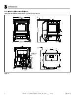
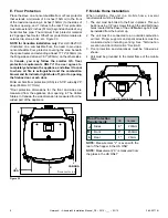
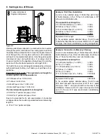
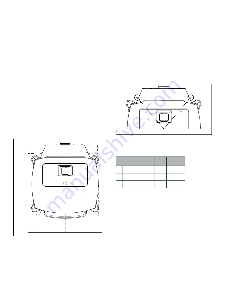
NOTE:
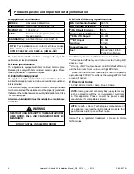
Measurement "L" is even with the
rear of the hopper in the US ONLY
NOTE:
Measurement “K” is measured from
the glass in the US ONLY
L
J
Floor Protection
Requirements
US
Canada
Sides
Rear
6"
200mm
1"
25mm
K
Front
6"
450mm
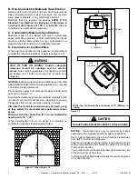
E. Floor Protection
Place the stove on a noncombustible floor or floor protector
that extends a minimum of 6 inches (152mm) to the front
of the load door opening, 6 inches (152mm) to the sides of
the door opening, and 1 inches to the rear. Floor protection
must also extend 2 inches (51mm) beyond each side of any
horizontal flue pipe. The minimum floor protector material
is 20 gauge sheet metal. Other floor protector materials are
ceramic tile, stone, brick, etc. Figure 3.3
NOTE for Canadian installation only:
Per ULC-S627-00,
if installed on a combustible floor, the need to provide a
noncombustible
floor protector
covering the area beneath
the
space heater
and extending at least 17.72” (450mm) on
the firing side and at least 7.87” (200mm) on the other sides.
In Canada, you may follow the smaller U.S. floor
protection requirements ONLY if the user agrees to
completely shut-down the appliance, and allow it to cool
to where all fire is extinguished and the combustion
blower and its indicator light shuts off, prior to opening
the firebox door or ash door.
Minimum Size floor protection (USA) is 25-7/8” wide By 28”
deep (658mm X 711mm).
*Floor protection dimensions for the front and sides are
measured from the appliance door opening in The United
States. In Canada, the side dimension is measured from the
widest part of the appliance.
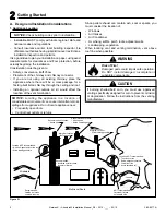
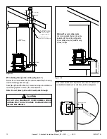
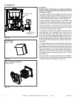
F. Mobile Home Installation
When installing this unit in a mobile home, several
requirements must be followed:
1. The unit must be bolted to the floor in places. This can
be done using 1/4” lag screws through the skid bolt down
holes located at the base of the unit.
Note:
Lag bolt must
be installed from the bottom up.
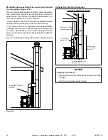
2. The unit must be connected to an outside combustion
air inlet. Proper supports and spark arresters must be
considered when installing venting. See “Termination
Location and Vent Information” Section D.
3. Floor protection and clearances must be followed as
shown.
4. Unit must be grounded to the metal frame of the mobile
home.
Figure 3.3
J
USA
K
L
J
CANADA
F
loor
protector
L
Install 1/4” lag bolts here.


